WWW.SURVIVALEBOOKS.COM<strong>FM</strong> 1-<strong>506</strong>nozzle. The wheels may or may not operate independently<strong>of</strong> one another, depending on engine type andturbine power requirements.Shaft RPM, gas flow rate, turbine inlet and outlettemperature and pressure, turbine exhaust velocity, andrequired power output must all be considered by thedesigner <strong>of</strong> the turbine. If the engine is equipped with adual compressor, the turbine must also be dual or "split."In this event, the forward part <strong>of</strong> the turbine (which drivesthe high-pressure compressor) can be single-stage becauseit receives high-energy gases directly from theburner and turns at a higher RPM than the turbine forthe low-presssure compressor. By the time the gasesreach the rear part <strong>of</strong> the turbine (which drives thelow-pressure compressor), they have expanded. Considerablymore blade area is needed if work or energybalance is to be maintained. To do a multistageturbine is used for the second part <strong>of</strong> the turbine (Figure3-15).high expansion ratio. This results in a large temperaturedrop in gases passing through the turbine and a coolturbine exhaust. If the engine is equipped with an afterburner,a cool exhaust enables more fuel to be burned inthe afterburner without exceeding the temperature limit<strong>of</strong> the construction materials used in the afterburner.The turbine wheel is a dynamically balanced unitconsisting <strong>of</strong> super alloy blades attached to a rotating disc.The base <strong>of</strong> the blade is usually a "fir tree" design toenable it to be firmly attached to the disc and still allowroom for expansion. In some turbines the rotating bladesare open at their outer perimeter. More commonly, theblade is shrouded at the tip. The shrouded blades forma band around the perimeter <strong>of</strong> the turbine wheel, whichserves to reduce blade vibrations. The weight <strong>of</strong> theshrouded tips is <strong>of</strong>fset because the shrouds permit thinner,more efficient blade sections than are otherwisepossible because <strong>of</strong> vibration limitations. Also, by actingin the same manner as aircraft wing tip fences, theshrouds improve the airflow characteristics and increasethe efficiency <strong>of</strong> the turbine. The shrouds also serve tocut down gas leakage around the tips <strong>of</strong> the turbineblades.Turbines are subjected to high speeds and hightemperatures. High speeds result in high centrifugalforces. Turbines must operate close to temperature limitsthat, if exceeded, lower the strength <strong>of</strong> the materials theyare constructed <strong>of</strong>. Turbine blades undergo distortion orlengthening known as "creep." Creep means that theblade stretches or elongates. This condition is cumulative.The rate <strong>of</strong> creep is determined by the load imposedon the turbine and the strength <strong>of</strong> the blade. The strength<strong>of</strong> the blade is determined by the temperature within theturbine. Since changes in pitch and creep are morepronounced if engine operating limits are not respectedthe pilot or flight engineer must closely observe thetemperature and RPM limits stipulated by the manufacturer.ConstructionThe turbine wheel is one <strong>of</strong> the most highly stressedengine parts. Not only must it operate at temperaturesup to approximately 1700ºF, but it must do sounder severecentrifugal loads imposed by high rotational speeds <strong>of</strong>over 40,000 RPM for small engines and 8000 RPM forlarger ones. Consequently, engine speed and turbineinlet temperature must be accurately controlled to keepthe turbine within safe operating limits.The turbine assembly is made <strong>of</strong> two main parts: thedisc and blades. This disc or wheel is a statically anddynamically balanced unit <strong>of</strong> specially alloyed steel. Itusually contains large percentages <strong>of</strong> chromium, nickel,and cobalt. After forging, the disc is machined all overand carefully inspected using X rays, magnetism, andother inspection methods for structural integrity. Theblades or buckets are attached to the disc by means <strong>of</strong> afir tree design to allow for different rates <strong>of</strong> expansionbetween the disc and the blade while still holding theblade firmly against centrifugal loads. The blade is keptfrom moving axially either by rivets, special locking tabsor devices, or another turbine stage.Some turbine blades are open at the outer perimeter(Figure 3-16); in others a shroud is used. The shroud actsto prevent blade-tip losses (gas leakage around the tips<strong>of</strong> the turbine blade) and excessive vibration. By actingin the same manner as aircraft wing tip fence, theshrouds improve airflow characteristics and increase turbineefficiency.Shrouds reduce resistance to distortion under highloads, which tend to twist the blade toward low pitch. Theshrouded blade has an aerodynamic advantage; thinnerblade sections can be used and tip lines can be reducedby using a knife-edge or labyrinth seal at this point.3-15
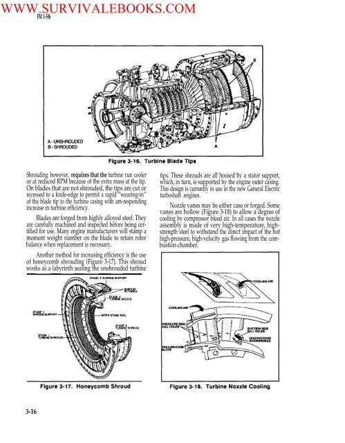
WWW.SURVIVALEBOOKS.COM<strong>FM</strong> 1-<strong>506</strong>Shrouding however, requires that the turbine run cooleror at reduced RPM because <strong>of</strong> the extra mass at the tip.On blades that are not shrouded, the tips are cut orrecessed to a knife-edge to permit a rapid “wearing-in”<strong>of</strong> the blade tip to the turbine casing with am-respondingincrease in turbine efficiency.Blades are forged from highly alloyed steel. Theyare carefully machined and inspected before being certifiedfor use. Many engine manufacturers will stamp amoment weight number on the blade to retain rotorbalance when replacement is necessary.Another method for increasing efficiency is the use<strong>of</strong> honeycomb shrouding (Figure 3-17). This shroudworks as a labyrinth sealing the unshrouded turbine. . . .tips. These shrouds are all housed by a stator support,which, in turn, is supported by the engine outer casing.This design is currently in use in the new General Electricturboshaft engines.Nozzle vanes may be either case or forged. Somevanes are hollow (Figure 3-18) to allow a degree <strong>of</strong>cooling by compressor bleed air. In all cases the nozzleassembly is made <strong>of</strong> very high-temperature, highstrengthsteel to withstand the direct impact <strong>of</strong> the hothigh-pressure, high-velocity gas flowing from the combustionchamber.3-16