

FM 1-506 Fundamentals of Aircraft Power Plants ... - Survival Books
FM 1-506 Fundamentals of Aircraft Power Plants ... - Survival Books
FM 1-506 Fundamentals of Aircraft Power Plants ... - Survival Books

Create successful ePaper yourself
Turn your PDF publications into a flip-book with our unique Google optimized e-Paper software.
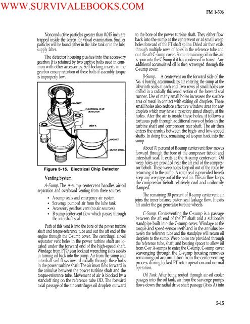
WWW.SURVIVALEBOOKS.COM<strong>FM</strong> 1-<strong>506</strong>Nonconductive particles greater than 0.015 inch aretrapped inside the screen for visual examination. Smallerparticles will be found either in the lube tank or in the lubesupply falter.The detector housing pushes into the accessorygearbox It is retained by two captive bolts used in commonwith other accessories. Self-locking inserts in thegearbox ensure retention <strong>of</strong> these bolts if assembly torqueis improperly low.Venting SystemA-Sump. The A-sump centervent handles air-oilseparation and overboard venting from these sources:A-sump seals and emergency air system.Scavenge pumped air from the lube tank.Accessory gearbox vent (no air sources).B-sump centervent flow which passes throughthe intershaft seal.Path <strong>of</strong> this vent is into the bore <strong>of</strong> the power turbineshaft and torque-reference tube and out the aft end <strong>of</strong> theengine through the C-sump cover. The centrifugal air-oilseparator vent holes in the power turbine shaft are locatedunder the forward end <strong>of</strong> the high-speed shaft.Windage from PTO gear locknut wrenching slots assistsin turning oil back into the sump. Air from the sump andintershaft seal flows inward radially through these holesin the power turbine shaft. The air must flow forward inthe annulus between the power turbine shaft and thetorque-reference tube. Movement <strong>of</strong> air is blocked by astand<strong>of</strong>f ring on the reference tube OD. The forwardaxial passage <strong>of</strong> the air centrifuges oil droplets outwardto the bore <strong>of</strong> the power turbine shaft. They either flowback into the sump at the centervent or at small weepholes forward <strong>of</strong> the PT shaft spline. Dried air then exitsthrough multiple rows <strong>of</strong> holes in the reference tube andout the aft C-sump cover. Some remaining oil in this airis spun into the C-Sump if it has condensed in transit. Anyadditional accumulated oil is then scavenged through theC-sump cover.B-Sump. A centervent on the forward side <strong>of</strong> theNo. 4 bearing accommodates air entering the sump at thelabyrinth seals at each end Two rows <strong>of</strong> small holes aredrilled in a radially thickened section <strong>of</strong> the forward sealrunner. Use <strong>of</strong> many small holes increases the surfacearea <strong>of</strong> metal in contact with exiting oil droplets. Thesesmall holes also reduce effective window area for anydroplets which may have a trajectory aimed directly at theholes. Ater the air is inside these holes, it follows atortuous path through additional rows <strong>of</strong> holes in theturbine shaft and compressor rear shaft. The air thenenters the annlus between the high- and low-speedshafts. In doing this, remaining oil is spun back into thesump.About 70 percent <strong>of</strong> B-sump centervent flow movesforward through the bore <strong>of</strong> the compresor tiebolt andintershaft seal. It exits at the A-sump centervent. Oilweep holes are provided near the aft end <strong>of</strong> the compressortiebolt. These weep holes keep oil out <strong>of</strong> the rotor byreturning it to the sump. A rotor seal is provided heretokeep any weepage out <strong>of</strong> the seal air. This airflow keepsthe compressor tiebolt relatively cool and uniformlyclamped.The remaining 30 percent <strong>of</strong> B-sump centervent airjoins the inner balance piston seal leakage flow. It exitsaft under the gas generator turbine wheels.C-Sump. Centerventing the C-sump is a passagebetween the aft end <strong>of</strong> the PT shaft and a stationarystandpipe built into the C-sump cover. Windage at thetorque and speed-sensor teeth and in the annulus betweenthe reference tube and the standpipe will return oildroplets to the sump. Weep holes are provided throughthe reference tube, shaft, and bearing spacer to allow oilfrom C-or A-sumps to enter the C-sump. C-sump coverscavenging through the C-sump housing removesremaining oil accumulation from the centerventingprocess during locked PT rotor operation and normaloperation.Oil Tank. After being routed through air-oil coolerpasages into the oil tank, air from the scavenge pumpsflows down the radial drive shaft passage (Axis A) into5-15


