

FM 1-506 Fundamentals of Aircraft Power Plants ... - Survival Books
FM 1-506 Fundamentals of Aircraft Power Plants ... - Survival Books
FM 1-506 Fundamentals of Aircraft Power Plants ... - Survival Books

Create successful ePaper yourself
Turn your PDF publications into a flip-book with our unique Google optimized e-Paper software.
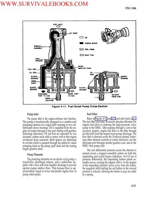
WWW.SURVIVALEBOOKS.COM<strong>FM</strong> 1-<strong>506</strong>Pump InletThe pump inlet is the engine-airframe fuel interface.The pump is mechanically designed as a cantileveredpumping element on a rigid shaft running in two oillubricatedsleeve bearings. Oil is supplied from the engineoil system through a face port mating with gearboxforbearing lubrication. Oil and fuel are separated by twodynamic carbon seals with a center vent to the engineoverboard drain manifold. Shaft splines are lubricatedby oil mist which is pumped through the splints by radialpumping holes in the pump quill shaft and the matingengine gearbox shaft.Pump ElementsThe pumping elements are an ejector or jet pump, amixed-flow centrifugal inducer, and a radial-flow impellerwith a flow path from impeller discharge to provideejector pump motive flow. This bypass flow is approximatelyequal to twice maximum engine flow atpump rated speed.Fuel FilterRefer to Figures 4-12 and 4-13 and refer back to 4-1.The fuel filter provides 30-micron absolute filtration forengine fuel prior to entering the high-pressure valvepump in the HMU. After passing through a core in theaccessory gearbox, engine fuel flows to the filter throughits inlet port from the engine boost pump discharge. Theflow then is directed across the 30-micron pleated, bariertypefilter element (outside to inside direction), out thedischarge port through another gearbox core, and to theHMU vane pump inlet.The fuel differential pressure across the element issensed across a magnet assembly piston on both theimpending and actual bypass indicators. At 8-10 psi <strong>of</strong>pressure differential, the impending button piston assemblymoves, carrying the magnet with it. As the magnet<strong>of</strong> the impending indicator moves away from the button,the magnetic field holding the red button in the inwardposition is reduced, allowing the button to pop out aidedby a spring.4-11


