

FM 1-506 Fundamentals of Aircraft Power Plants ... - Survival Books
FM 1-506 Fundamentals of Aircraft Power Plants ... - Survival Books
FM 1-506 Fundamentals of Aircraft Power Plants ... - Survival Books

You also want an ePaper? Increase the reach of your titles
YUMPU automatically turns print PDFs into web optimized ePapers that Google loves.
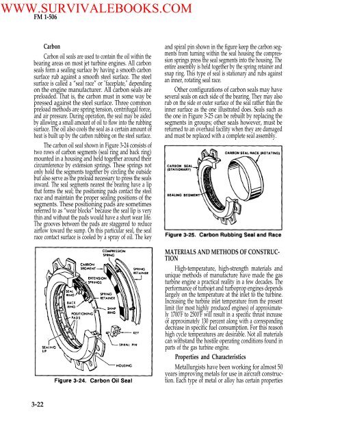
WWW.SURVIVALEBOOKS.COM<strong>FM</strong> 1-<strong>506</strong>CarbonCarbon oil seals are used to contain the oil within thebearing areas on most jet turbine engines. All carbonseals form a sealing surface by having a smooth carbonsurface rub against a smooth steel surface. The steelsurface is called a “seal race” or "faceplate," dependingon the engine manufacturer. All carbon seals arepreloaded. That is, the carbon must in some way bepressed against the steel surface. Three commonpreload methods are spring tension, centrifugal force,and air pressure. During operation, the seal may be aidedby allowing a small amount <strong>of</strong> oil to flow into the rubbingsurface. The oil also cools the seal as a certain amount <strong>of</strong>heat is built up by the carbon rubbing on the steel surface.The carbon oil seal shown in Figure 3-24 consists <strong>of</strong>two rows <strong>of</strong> carbon segments (seal ring and back ring)mounted in a housing and held together around theircircumference by extension springs. These springs notonly hold the segments together by circling the outsidebut also serve as the preload necessary to press the sealsinward. The seal segments nearest the bearing have a lipthat forms the seal; the positioning pads contact the steelrace and maintain the proper sealing positions <strong>of</strong> thesegments. These positioning pads are sometimesreferred to as “wear blocks” because the seal lip is verythin and without the pads would have a short wear life.The grooves between the pads are staggered to reduceairflow toward the sump. On this particular seal, the sealrace contact surface is cooled by a spray <strong>of</strong> oil. The keyand spiral pin shown in the figure keep the carbon segmentsfrom turning within the seal housing the compressionsprings press the seal segments into the housing. Theentire assembly is held together by the spring retainer andsnap ring. This type <strong>of</strong> seal is stationary and rubs againstan inner, rotating seal race.Other configurations <strong>of</strong> carbon seals may haveseveral seals on each side <strong>of</strong> the bearing. They may alsorub on the side or outer surface <strong>of</strong> the seal rather than theinner surface as the one illustrated does. Seals such asthe one in Figure 3-25 can be rebuilt by replacing thesegments in groups; other seals however, must bereturned to an overhaul facility when they are damagedand must be replaced with a complete seal assembly.MATERIALS AND METHODS OF CONSTRUCTIONHigh-temperature, high-strength materials andunique methods <strong>of</strong> manufacture have made the gasturbine engine a practical reality in a few decades. Theperformance <strong>of</strong> turbojet and turboprop engines dependslargely on the temperature at the inlet to the turbine.Increasing the turbine inlet temperature from the presentlimit (for most highly produced engines) <strong>of</strong> approximately1700 0 F to 2500 0 F will result in a specific thrust increase<strong>of</strong> approximately 130 percent along with a correspondingdecrease in specific fuel consumption. For this reasonhigh cycle temperatures are desirable. Not all materialscan withstand the hostile operating conditions found inparts <strong>of</strong> the gas turbine engine.Properties and CharacteristicsMetallurgists have been working for almost 50years improving metals for use in aircraft construction.Each type <strong>of</strong> metal or alloy has certain properties3-22


