

FM 1-506 Fundamentals of Aircraft Power Plants ... - Survival Books
FM 1-506 Fundamentals of Aircraft Power Plants ... - Survival Books
FM 1-506 Fundamentals of Aircraft Power Plants ... - Survival Books

Create successful ePaper yourself
Turn your PDF publications into a flip-book with our unique Google optimized e-Paper software.
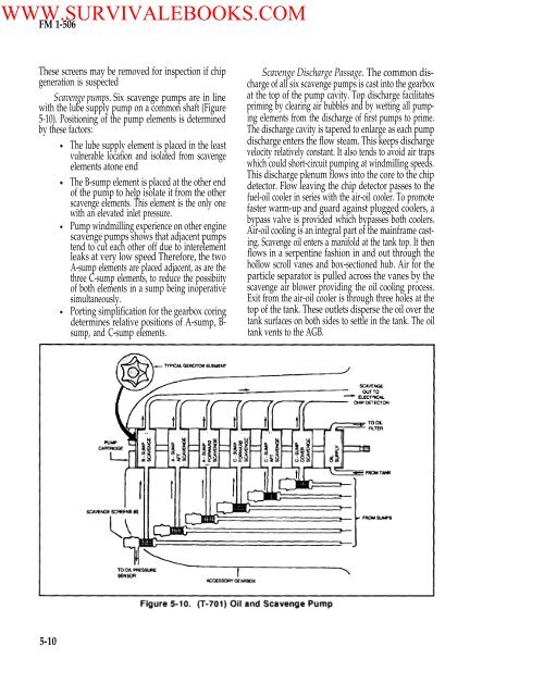
WWW.SURVIVALEBOOKS.COM<strong>FM</strong> 1-<strong>506</strong>These screens may be removed for inspection if chipgeneration is suspectedScavenge pumps. Six scavenge pumps are in linewith the lube supply pump on a common shaft (Figure5-10). Positioning <strong>of</strong> the pump elements is determinedby these factors:The lube supply element is placed in the leastvulnerable location and isolated from scavengeelements atone endThe B-sump element is placed at the other end<strong>of</strong> the pump to help isolate it from the otherscavenge elements. This element is the only onewith an elevated inlet pressure.Pump windmilling experience on other enginescavenge pumps shows that adjacent pumpstend to cut each other <strong>of</strong>f due to interelementleaks at very low speed Therefore, the twoA-sump elements are placed adjacent, as are thethree C-sump elements, to reduce the possibiity<strong>of</strong> both elements in a sump being inoperativesimultaneously.Porting simplification for the gearbox coringdetermines relative positions <strong>of</strong> A-sump, B-sump, and C-sump elements.Scavenge Discharge Passage. The common discharge<strong>of</strong> all six scavenge pumps is cast into the gearboxat the top <strong>of</strong> the pump cavity. Top discharge facilitatespriming by clearing air bubbles and by wetting all pumpingelements from the discharge <strong>of</strong> first pumps to prime.The discharge cavity is tapered to enlarge as each pumpdischarge enters the flow steam. This keeps dischargevelocity relatively constant. It also tends to avoid air trapswhich could short-circuit pumping at windmilling speeds.This discharge plenum flows into the core to the chipdetector. Flow leaving the chip detector passes to thefuel-oil cooler in series with the air-oil cooler. To promotefaster warm-up and guard against plugged coolers, abypass valve is provided which bypasses both coolers.Air-oil cooling is an integral part <strong>of</strong> the mainframe casting.Scavenge oil enters a manifold at the tank top. It thenflows in a serpentine fashion in and out through thehollow scroll vanes and box-sectioned hub. Air for theparticle separator is pulled across the vanes by thescavenge air blower providing the oil cooling process.Exit from the air-oil cooler is through three holes at thetop <strong>of</strong> the tank. These outlets disperse the oil over thetank surfaces on both sides to settle in the tank. The oiltank vents to the AGB.5-10


