IFC 110 F V2.0 IFC 110 F-EEx V2.0 - Krohne
IFC 110 F V2.0 IFC 110 F-EEx V2.0 - Krohne
IFC 110 F V2.0 IFC 110 F-EEx V2.0 - Krohne
You also want an ePaper? Increase the reach of your titles
YUMPU automatically turns print PDFs into web optimized ePapers that Google loves.
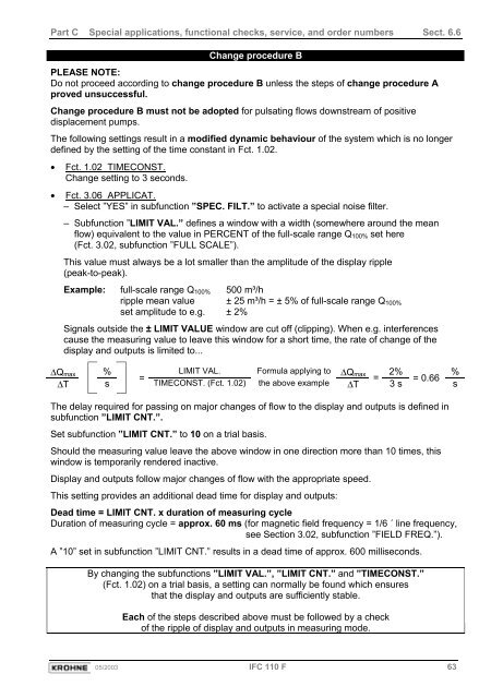
Part C Special applications, functional checks, service, and order numbers Sect. 6.6Change procedure BPLEASE NOTE:Do not proceed according to change procedure B unless the steps of change procedure Aproved unsuccessful.Change procedure B must not be adopted for pulsating flows downstream of positivedisplacement pumps.The following settings result in a modified dynamic behaviour of the system which is no longerdefined by the setting of the time constant in Fct. 1.02.• Fct. 1.02 TIMECONST.Change setting to 3 seconds.• Fct. 3.06 APPLICAT.– Select ”YES” in subfunction ”SPEC. FILT.” to activate a special noise filter.– Subfunction ”LIMIT VAL.” defines a window with a width (somewhere around the meanflow) equivalent to the value in PERCENT of the full-scale range Q 100% set here(Fct. 3.02, subfunction ”FULL SCALE”).This value must always be a lot smaller than the amplitude of the display ripple(peak-to-peak).Example: full-scale range Q 100% 500 m³/hripple mean value ± 25 m³/h = ± 5% of full-scale range Q 100%set amplitude to e.g. ± 2%Signals outside the ± LIMIT VALUE window are cut off (clipping). When e.g. interferencescause the measuring value to leave this window for a short time, the rate of change of thedisplay and outputs is limited to...∆Q max % LIMIT VAL. Formula applying to ∆Q max 2% %== = 0.66∆T sTIMECONST. (Fct. 1.02) the above example ∆T 3 ssThe delay required for passing on major changes of flow to the display and outputs is defined insubfunction ”LIMIT CNT.”.Set subfunction ”LIMIT CNT.” to 10 on a trial basis.Should the measuring value leave the above window in one direction more than 10 times, thiswindow is temporarily rendered inactive.Display and outputs follow major changes of flow with the appropriate speed.This setting provides an additional dead time for display and outputs:Dead time = LIMIT CNT. x duration of measuring cycleDuration of measuring cycle = approx. 60 ms (for magnetic field frequency = 1/6 ´ line frequency,see Section 3.02, subfunction ”FIELD FREQ.”).A ”10” set in subfunction ”LIMIT CNT.” results in a dead time of approx. 600 milliseconds.By changing the subfunctions ”LIMIT VAL.”, ”LIMIT CNT.” and ”TIMECONST.”(Fct. 1.02) on a trial basis, a setting can normally be found which ensuresthat the display and outputs are sufficiently stable.Each of the steps described above must be followed by a checkof the ripple of display and outputs in measuring mode.05/2003 <strong>IFC</strong> <strong>110</strong> F 63


