IFC 110 F V2.0 IFC 110 F-EEx V2.0 - Krohne
IFC 110 F V2.0 IFC 110 F-EEx V2.0 - Krohne
IFC 110 F V2.0 IFC 110 F-EEx V2.0 - Krohne
You also want an ePaper? Increase the reach of your titles
YUMPU automatically turns print PDFs into web optimized ePapers that Google loves.
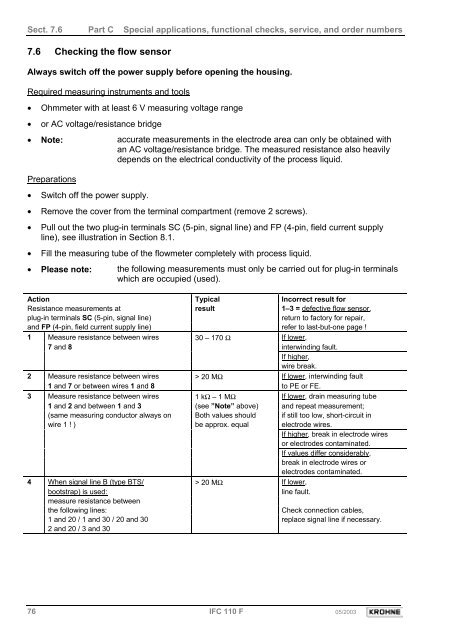
Sect. 7.6 Part C Special applications, functional checks, service, and order numbers7.6 Checking the flow sensorAlways switch off the power supply before opening the housing.Required measuring instruments and tools• Ohmmeter with at least 6 V measuring voltage range• or AC voltage/resistance bridge• Note: accurate measurements in the electrode area can only be obtained withan AC voltage/resistance bridge. The measured resistance also heavilydepends on the electrical conductivity of the process liquid.Preparations• Switch off the power supply.• Remove the cover from the terminal compartment (remove 2 screws).• Pull out the two plug-in terminals SC (5-pin, signal line) and FP (4-pin, field current supplyline), see illustration in Section 8.1.• Fill the measuring tube of the flowmeter completely with process liquid.• Please note: the following measurements must only be carried out for plug-in terminalswhich are occupied (used).Action Typical Incorrect result forResistance measurements at result 1–3 = defective flow sensor,plug-in terminals SC (5-pin, signal line)return to factory for repair,and FP (4-pin, field current supply line) refer to last-but-one page !1 Measure resistance between wires 30 – 170 Ω If lower,7 and 8 interwinding fault.If higher,wire break.2 Measure resistance between wires > 20 MΩ If lower, interwinding fault1 and 7 or between wires 1 and 8 to PE or FE.3 Measure resistance between wires 1 kΩ – 1 MΩ If lower, drain measuring tube1 and 2 and between 1 and 3 (see ”Note” above) and repeat measurement;(same measuring conductor always on Both values should if still too low, short-circuit inwire 1 ! ) be approx. equal electrode wires.If higher, break in electrode wiresor electrodes contaminated.If values differ considerably,break in electrode wires orelectrodes contaminated.4 When signal line B (type BTS/ > 20 MΩ If lower,bootstrap) is used:line fault.measure resistance betweenthe following lines:Check connection cables,1 and 20 / 1 and 30 / 20 and 30 replace signal line if necessary.2 and 20 / 3 and 3076 <strong>IFC</strong> <strong>110</strong> F 05/2003


