

IFC 110 F V2.0 IFC 110 F-EEx V2.0 - Krohne
IFC 110 F V2.0 IFC 110 F-EEx V2.0 - Krohne
IFC 110 F V2.0 IFC 110 F-EEx V2.0 - Krohne

Create successful ePaper yourself
Turn your PDF publications into a flip-book with our unique Google optimized e-Paper software.
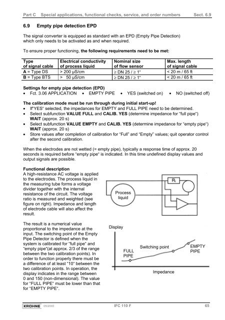
Part C Special applications, functional checks, service, and order numbers Sect. 6.96.9 Empty pipe detection EPDThe signal converter is equipped as standard with an EPD (Empty Pipe Detection)which only needs to be activated as and when required.To ensure proper functioning, the following requirements need to be met:Typeof signal cableElectrical conductivityof process liquidNominal sizeof flow sensorMax. lengthof signal cableA = Type DS > 200 µS/cm ≥ DN 25 / ≥ 1“ < 20 m / 65 ftB = Type BTS > 50 µS/cm ≥ DN 25 / ≥ 1“ < 20 m / 65 ftSettings for empty pipe detection (EPD)• Fct. 3.06 APPLICATION • EMPTY PIPE • YES (switched on) • NO (switched off)The calibration mode must be run through during initial start-up!• If“YES“ selected, the impedances for EMPTY and FULL PIPE need to be determined.• Select subfunction VALUE FULL and CALIB. YES (determine impedance for “full pipe“)WAIT (approx. 20 s)• Select subfunction VALUE EMPTY and CALIB. YES (determine impedance for “empty pipe“)WAIT (approx. 20 s)• Store values after completion of calibration for “Full” and “Empty” values; quit operator controlafter the second calibration.When the electrodes are not wetted (= empty pipe), typically a response time of approx. 20seconds is required before “empty pipe“ is indicated. In this time undefined display values andoutput signals are possible.Functional descriptionA high-resistance AC voltage is appliedto the electrodes. The process liquid inthe measuring tube forms a voltagedivider together with the internalresistance of the circuit. The voltageratio is measured and weighted (seefigure on right). Impedance and lengthof electrode cable will also affect theresult.ProcessliquidThe result is a numerical valueproportional to the impedance at theinput. The switching point of the EmptyPipe Detector is defined when thesystem is calibrated for “full pipe“ and“empty pipe“(at approx. 2/3 of the rangebetween the two calibration points). Inorder to function properly there must bea difference of at least “10“ between thetwo calibration points. In operation, thedisplay indicates in the range between0 and 150 (non-dimensional). The valuefor “FULL PIPE“ must be lower than thatfor “EMPTY PIPE“.DisplayFULLPIPESwitching pointImpedanceEMPTYPIPE05/2003 <strong>IFC</strong> <strong>110</strong> F 65


