

IFC 110 F V2.0 IFC 110 F-EEx V2.0 - Krohne
IFC 110 F V2.0 IFC 110 F-EEx V2.0 - Krohne
IFC 110 F V2.0 IFC 110 F-EEx V2.0 - Krohne

You also want an ePaper? Increase the reach of your titles
YUMPU automatically turns print PDFs into web optimized ePapers that Google loves.
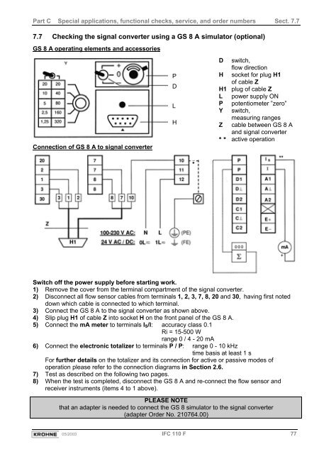
Part C Special applications, functional checks, service, and order numbers Sect. 7.77.7 Checking the signal converter using a GS 8 A simulator (optional)GS 8 A operating elements and accessoriesConnection of GS 8 A to signal converterPDLHD switch,flow directionH socket for plug H1of cable ZH1 plug of cable ZL power supply ONP potentiometer ”zero”Y switch,measuring rangesZ cable between GS 8 Aand signal converter* * active operationSwitch off the power supply before starting work.1) Remove the cover from the terminal compartment of the signal converter.2) Disconnect all flow sensor cables from terminals 1, 2, 3, 7, 8, 20 and 30, having first noteddown which cable is connected to which terminal.3) Connect the GS 8 A to the signal converter as shown above.4) Slip plug H1 of cable Z into socket H on the front panel of the GS 8 A.5) Connect the mA meter to terminals I S /I: accuracy class 0.1Ri = 15-500 Wrange 0 / 4 - 20 mA6) Connect the electronic totalizer to terminals P / P: range 0 - 10 kHztime basis at least 1 sFor further details on the totalizer and its connection for active or passive modes ofoperation please refer to the connection diagrams in Section 2.6.7) Test as described on the following two pages.8) When the test is completed, disconnect the GS 8 A and re-connect the flow sensor andreceiver instruments (items 4 to 1 above).PLEASE NOTEthat an adapter is needed to connect the GS 8 simulator to the signal converter(adapter Order No. 210764.00)05/2003 <strong>IFC</strong> <strong>110</strong> F 77


