GS1 EPC Tag Data Standard 1.6 - Indicod-Ecr
GS1 EPC Tag Data Standard 1.6 - Indicod-Ecr
GS1 EPC Tag Data Standard 1.6 - Indicod-Ecr
- No tags were found...

You also want an ePaper? Increase the reach of your titles
YUMPU automatically turns print PDFs into web optimized ePapers that Google loves.
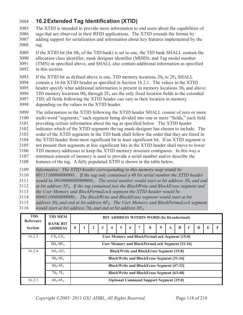
30843085308630873088308930903091309230933094309530963097309830993100310131023103310431053106310731083109311031113112311331143115311616.2Extended <strong>Tag</strong> Identification (XTID)The XTID is intended to provide more information to end users about the capabilities oftags that are observed in their RFID applications. The XTID extends the format byadding support for serialization and information about key features implemented by thetag.If the XTID bit (bit 08 h of the TID bank) is set to one, the TID bank SHALL contain theallocation class identifier, mask designer identifier (MDID), and <strong>Tag</strong> model number(TMN) as specified above, and SHALL also contain additional information as specifiedin this section.If the XTID bit as defined above is one, TID memory locations 20 h to 2F h SHALLcontain a 16-bit XTID header as specified in Section 16.2.1. The values in the XTIDheader specify what additional information is present in memory locations 30 h and above.TID memory locations 00 h through 2F h are the only fixed location fields in the extendedTID; all fields following the XTID header can vary in their location in memorydepending on the values in the XTID header.The information in the XTID following the XTID header SHALL consist of zero or moremulti-word “segments,” each segment being divided into one or more “fields,” each fieldproviding certain information about the tag as specified below. The XTID headerindicates which of the XTID segments the tag mask-designer has chosen to include. Theorder of the XTID segments in the TID bank shall follow the order that they are listed inthe XTID header from most significant bit to least significant bit. If an XTID segment isnot present then segments at less significant bits in the XTID header shall move to lowerTID memory addresses to keep the XTID memory structure contiguous. In this way aminimum amount of memory is used to provide a serial number and/or describe thefeatures of the tag. A fully populated XTID is shown in the table below.Informative: The XTID header corresponding to this memory map would be0011110000000000 2 . If the tag only contained a 48 bit serial number the XTID headerwould be 0010000000000000 2 . The serial number would start at bit address 30 h and endat bit address 5F h . If the tag contained just the BlockWrite and BlockErase segment andthe User Memory and BlockPermaLock segment the XTID header would be0000110000000000 2 . The BlockWrite and BlockErase segment would start at bitaddress 30 h and end at bit address 6F h . The User Memory and BlockPermaLock segmentwould start at bit address 70 h and end at bit address 8F h .TDSReferenceSectionTID MEMBANK BITADDRESSBIT ADDRESS WITHIN WORD (In Hexadecimal)0 1 2 3 4 5 6 7 8 9 A B C D E F16.2.5 C0 h -CF h User Memory and BlockPermaLock Segment [15:0]B0 h -BF h User Memory and BlockPermaLock Segment [31:16]16.2.4 A0 h -AF h BlockWrite and BlockErase Segment [15:0]90 h -9F h BlockWrite and BlockErase Segment [31:16]80 h -8F h BlockWrite and BlockErase Segment [47:32]70 h -7F h BlockWrite and BlockErase Segment [63:48]16.2.3 60 h -6F h Optional Command Support Segment [15:0]Copyright ©2005- 2011 <strong>GS1</strong> AISBL, All Rights Reserved. Page 118 of 218