FIRST STEPS TOWARD SPACE - Smithsonian Institution Libraries
FIRST STEPS TOWARD SPACE - Smithsonian Institution Libraries
FIRST STEPS TOWARD SPACE - Smithsonian Institution Libraries

Create successful ePaper yourself
Turn your PDF publications into a flip-book with our unique Google optimized e-Paper software.
NUMBER 10<br />
In addition to a study of orbital paths (corresponding<br />
to our transfer orbits), this work includes<br />
considerations on the application of relativity to<br />
energy radiation (REP anticipated photonic propulsion,<br />
study of which has been undertaken recently<br />
in some countries).<br />
The principle of multistage rockets and the calculations<br />
of mass ratios presented by REP stimulated<br />
the work of Louis Damblanc, who in 1936<br />
was awarded a patent for "self-driven projectiles<br />
whose propulsive charge is distributed in several<br />
combustion stages along the axis of the rocket." 50<br />
REP also foresaw the advantage of rockets for the<br />
study of the aurora borealis, which is the purpose<br />
of many current sounding rockets.<br />
After the publication of the supplement to his<br />
book, REP was awarded his second annual Grand<br />
Prize by the Societe des Ing^nieurs Civils de France.<br />
On 22 June 1936, he became a member of the<br />
Acaddmie des Sciences in the division "applications<br />
de la science a l'industrie." 51<br />
Some Experimental Works<br />
Let us review some of REP : s experimental works<br />
that enabled him to solve certain problems in an<br />
original way (we owe the details of paragraphs 1—4<br />
to Ing£nieur General J.-J. Barre, who sent us copies<br />
of certain of REP's reports, the originals of which<br />
have been destroyed).<br />
1. Method of injecting fuel and oxidizer into the<br />
combustion chamber.—REP first tried using a device<br />
including volumetric pumps driven by a sort<br />
of gas turbine turned by part of the jet from the<br />
nozzle. This design was abandoned because of the<br />
difficulties due to pump lubrication and the poor<br />
behavior of the liquid-oxygen fittings. He then used<br />
pressurized tanks for feeding the fuel and oxidizer.<br />
This system worked by the pressure of an inert gas<br />
on the fuel and by the action of a heater that raised<br />
the pressure of the oxygen and vaporized part of it.<br />
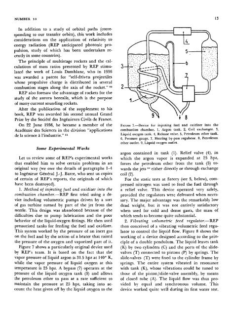
Figure 7 shows a particularly original device used<br />
by REP's team. It is based on the fact that the<br />
vapor pressure of liquid argon is 31.5 hpz at 140° K,<br />
while the vapor pressure of liquid oxygen at this<br />
temperature is 25 hpz. A bypass (7) operates at the<br />
pressure of the liquid oxygen tank (3) and allows<br />
the petroleum ether to pass at a rate sufficient to<br />
maintain the pressure at 25 hpz, taking into account<br />
the heat given off by the liquid oxygen to the<br />
FIGURE 7.—Device for injecting fuel and oxidizer into the<br />
combustion chamber. 1, Argon tank. 2, Coil exchanger. 3,<br />
Liquid oxygen tank. 4, Release valve. 5, Petroleum ether tank.<br />
6, Pressure gauge. 7, Heating by-pass regulator. 8, Petroleum<br />
ether outlet. 9, Liquid oxygen outlet.<br />
argon contained in tank (1). Relief valve (4), in<br />
which the argon vapor is expanded at 25 hpz,<br />
forces the petroleum ether from the tank (5) towards<br />
the jets 52 either directly or through exchange<br />
coil (2).<br />
For the static tests at Satory (see 5, below), compressed<br />
nitrogen was used to feed the fuel through<br />
a relief valve. This device operated very safely,<br />
provided the regulators were defrosted when necessary.<br />
The major advantage was the remarkably low<br />
dead weight, but it was not entirely satisfactory<br />
when used for cold and dense gases, the mass of<br />
which tends to become quite substantial.<br />
2. Vibrating volumetric feed regulator.—REP<br />
then conceived of a vibrating volumetric feed regulator<br />
to control the liquid flow. Figure 8 shows the<br />
working of a device designed according to the principle<br />
of a double pendulum. The liquid leaves tank<br />
(K) by two cylinders (C) and the ports of the slidevalves<br />
(T) connected to pistons (P) by springs. The<br />
slide-valves (T) were fixed to the cylinder frame by<br />
springs. The entire system vibrated in resonance<br />
with tank (K), whose vibrations could be tuned to<br />
those of the piston/slide-valve assembly, by means<br />
of closed tube (A). The liquid flow was thus provided<br />
by equal and synchronous volume. This<br />
device worked quite well during its first water test.<br />
13