special - Alu-web.de
special - Alu-web.de
special - Alu-web.de

You also want an ePaper? Increase the reach of your titles
YUMPU automatically turns print PDFs into web optimized ePapers that Google loves.
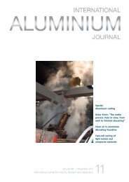
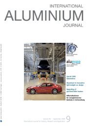
ALUMINIUM EXTRUSION INDUSTRY<br />
file cross-section is 56 × 5 mm 2 and<br />
the press ratio is 1 : 60. All profiles<br />
were extru<strong>de</strong>d at almost homogenous<br />
temperature conditions and a constant<br />
profile speed of v e = 3.6 m/min.<br />
Threading of continuously<br />
reinforced aluminium profiles<br />
The application and extend of use of<br />
new materials is strongly connected to<br />
their machinability. Special mechanical<br />
or physical properties, beneficial<br />
for the application of materials, can<br />
be disadvantageous for machining<br />
operations. The combination of different<br />
materials within a composite allows<br />
a combination of different properties;<br />
but if both materials have to be<br />
cut or formed in one process with the<br />
same tool, it usually evokes a compromise<br />
in machining. Since the gains<br />
from using composite materials like<br />
continuously reinforced aluminium<br />
profiles are high, the challenge faced<br />
by research is to <strong>de</strong>termine suitable<br />
machining operations. Therefore, experimental<br />
investigations concerning<br />
flow-drilling and threading of steelwire<br />
reinforced flat profiles have been<br />
conducted.<br />
Flow-drilling is a chipless method<br />
of producing bushings in thin-walled<br />
structures like sheet metals, tubes or<br />
extrusions by using a polygon-shaped<br />
pin with conical head ma<strong>de</strong> of cemented<br />
carbi<strong>de</strong>. The pin can be used<br />
on drilling machines or machining<br />
centres where it is accelerated up to a<br />
<strong>de</strong>fined rotational speed and fed into<br />
the direction of the workpiece. The<br />
pin is pressed against the workpiece<br />
material either with a <strong>de</strong>fined force,<br />
or by using a <strong>de</strong>fined feed. Friction<br />
between the tool and the workpiece<br />
Fig. 3: Extrusion forces double-T-profile<br />
generates heat that lowers the yield<br />
strength of the workpiece material.<br />
Forming of the workpiece material<br />
becomes easier. By pushing the pin<br />
further into the workpiece, material,<br />
displaced by the tool, yields in opposite<br />
direction of the feed first and in<br />
direction of the feed later. The material<br />
yielding towards the spindle can<br />
either be cut off by countersink cutting<br />
edges of the pin, or can be formed<br />
to a <strong>de</strong>fined flange with a shoul<strong>de</strong>r<br />
of the pin. The material displaced in<br />
the direction of the feed is formed<br />
to a stable collar which can be used<br />
for threading, in addition to the wall<br />
thickness of the profile.<br />
Threading, as a subsequent machining<br />
operation after flow-drilling,<br />
can be carried out via different machining<br />
operations. Threads can either<br />
be cut by tapping or thread milling,<br />
or formed by thread forming. In<br />
contrast to the conventional method<br />
of tapping, the axial forces acting on<br />
the workpiece are usually smaller<br />
when using thread milling, which can<br />
be advantageous for machining thinwalled<br />
profiles. Additionally, cutting<br />
parameters can be varied in a wi<strong>de</strong>r<br />
range. The main advantage of the<br />
forming process compared to cutting<br />
operations is the resulting grain flow<br />
within the workpiece material [6].<br />
The workpiece material is strengthened<br />
by work har<strong>de</strong>ning. Since no<br />
chips are created, chip packing cannot<br />
occur and so process reliability is<br />
increased. The field of application is<br />
limited to certain materials. A tensile<br />
strength of R m≤1200 N/mm 2 should<br />
not be excee<strong>de</strong>d and the elongation<br />
after fracture should be more than<br />
A ≥ 5 - 8% to make cold forming feasible<br />
[7]. While the aluminium matrix<br />
material of the<br />
composite extrusions<br />
meets<br />
the requirements,<br />
the tensile<br />
strength of<br />
the reinforcement<br />
exceeds<br />
the limit. Experimentalinvestigations<br />
on the<br />
composite profiles<br />
were conducted<br />
to reveal<br />
the effect of the reinforcement on the<br />
profiles characteristics during thread<br />
forming.<br />
Experimental setup<br />
The investigations have been carried<br />
out using flow-drilling tools with countersink<br />
cutting edges to create a flat<br />
surface on the entry si<strong>de</strong>. The forming<br />
part of the tool has a polygonal shape<br />
with four facets. Threading was done<br />
with different tools. The tools used for<br />
tapping and thread forming are ma<strong>de</strong><br />
from high speed steel coated with<br />
TiN in case of thread forming, and<br />
TiCN in case of tapping. The thread<br />
milling tool is ma<strong>de</strong> from cemented<br />
carbi<strong>de</strong> and coated with TiAlN. The<br />
different substrates were chosen to<br />
cope with the <strong>special</strong> characteristics<br />
of the processes. The tapping and the<br />
thread forming tools are subjected<br />
to tensile and torsional loads due to<br />
synchronisation errors of the machine<br />
tool. Therefore, the substrate of these<br />
tools must be ductile. Thread milling<br />
tools are mainly stressed by radial<br />
loads, making a rigid substrate necessary.<br />
Moreover, cemented carbi<strong>de</strong><br />
is favourable for high cutting speeds.<br />
The different titanium-based coatings<br />
give the tools a hard, wear resistant<br />
surface. Flat profiles with seven solid<br />
steel wires, arranged in a regular pattern,<br />
were machined using different<br />
three-axis machining centres. The position<br />
of the hole relative to the positions<br />
of the reinforcing elements was<br />
varied and a non-reinforced aluminium<br />
profile was machined as reference.<br />
The positions and the direction<br />
of the sectional view for a qualitative<br />
analysis of the lateral area are shown<br />
in Fig. 4.<br />
Flow-drilling investigations<br />
The investigations concerning the<br />
flow-drilling process take the feed as<br />
an additional influencing factor into<br />
account. A feed of f = 0.025 mm up to f<br />
= 0.1 mm was analysed with a peripheral<br />
speed of v c = 30 m/min. The profiles<br />
are split into parts after machining.<br />
The corresponding sections are<br />
shown in Fig. 5. The outer form of the<br />
collar and the material distribution in<br />
the collar is comparable in all cases.<br />
38 ALUMINIUM · 4/2010