$95 HD/LINKer - Invensys Rail
$95 HD/LINKer - Invensys Rail
$95 HD/LINKer - Invensys Rail

Create successful ePaper yourself
Turn your PDF publications into a flip-book with our unique Google optimized e-Paper software.
MAIN WINDOW DESCRIPTION<br />
6.1.1 Main Tool Bar<br />
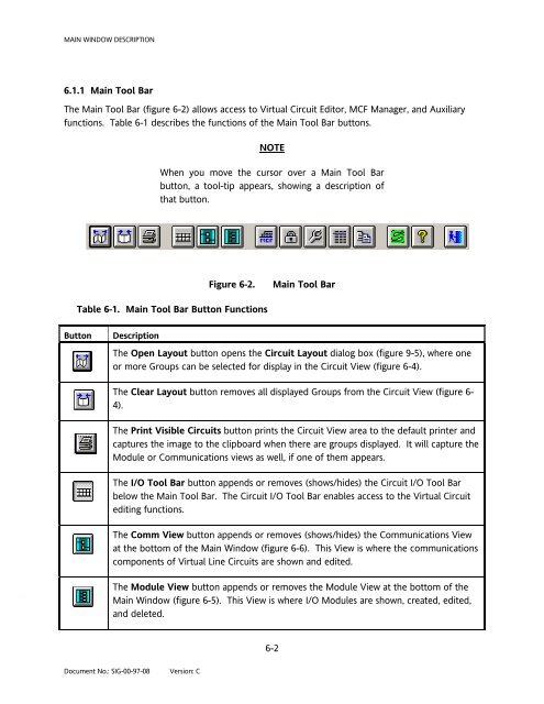
The Main Tool Bar (figure 6-2) allows access to Virtual Circuit Editor, MCF Manager, and Auxiliary<br />
functions. Table 6-1 describes the functions of the Main Tool Bar buttons.<br />
Document No.: SIG-00-97-08 Version: C<br />
NOTE<br />
When you move the cursor over a Main Tool Bar<br />
button, a tool-tip appears, showing a description of<br />
that button.<br />
Table 6-1. Main Tool Bar Button Functions<br />
Figure 6-2. Main Tool Bar<br />
Button Description<br />
The Open Layout button opens the Circuit Layout dialog box (figure 9-5), where one<br />
or more Groups can be selected for display in the Circuit View (figure 6-4).<br />
The Clear Layout button removes all displayed Groups from the Circuit View (figure 6-<br />
4).<br />
The Print Visible Circuits button prints the Circuit View area to the default printer and<br />
captures the image to the clipboard when there are groups displayed. It will capture the<br />
Module or Communications views as well, if one of them appears.<br />
The I/O Tool Bar button appends or removes (shows/hides) the Circuit I/O Tool Bar<br />
below the Main Tool Bar. The Circuit I/O Tool Bar enables access to the Virtual Circuit<br />
editing functions.<br />
The Comm View button appends or removes (shows/hides) the Communications View<br />
at the bottom of the Main Window (figure 6-6). This View is where the communications<br />
components of Virtual Line Circuits are shown and edited.<br />
The Module View button appends or removes the Module View at the bottom of the<br />
Main Window (figure 6-5). This View is where I/O Modules are shown, created, edited,<br />
and deleted.<br />
6-2