$95 HD/LINKer - Invensys Rail
$95 HD/LINKer - Invensys Rail
$95 HD/LINKer - Invensys Rail

Create successful ePaper yourself
Turn your PDF publications into a flip-book with our unique Google optimized e-Paper software.
9.3.2 Circuit I/O<br />
Document No.: SIG-00-97-08 Version: C<br />
9-13<br />
VIRTUAL CIRCUIT EDITOR<br />
Circuit I/O configurations are shown by stylized icons within the bounds of a Group column. Groups<br />
are shown within the circuit view as shown in figure 9-10. Also shown are two rectangular module<br />
icons within the Module View of each Group. The first, labeled R<strong>HD</strong>, represents the <strong>HD</strong>/LINK I/O<br />
module to be configured. The second, labeled SSR, represents the Group’s Spread Spectrum Radio.<br />
Inclusion of the Group’s SSR within the Module View is optional.<br />
9.3.2.1 Virtual Circuit Creation<br />
Virtual circuit creation requires the following:<br />
� The placement of specific I/O icons within the selected Groups.<br />
� The entering of circuit I/O information.<br />
� The creation of Virtual circuits between complementary I/O configurations (including Cut I/O) of<br />
adjacent Groups.<br />
To create a Virtual Circuit, proceed as follows:<br />
1. Click on the Termination or Cut I/O icon representing the desired I/O configuration.<br />
2. SDFS Click on the Group column. The cursor changes to an I/O icon..<br />
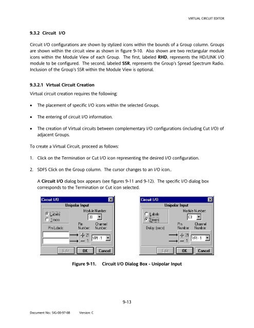
A Circuit I/O dialog box appears (see figures 9-11 and 9-12). The specific I/O dialog box<br />
corresponds to the Termination or Cut icon selected.<br />
Figure 9-11. Circuit I/O Dialog Box - Unipolar Input