$95 HD/LINKer - Invensys Rail
$95 HD/LINKer - Invensys Rail
$95 HD/LINKer - Invensys Rail

You also want an ePaper? Increase the reach of your titles
YUMPU automatically turns print PDFs into web optimized ePapers that Google loves.
8.3 COMMUNICATIONS SESSIONS<br />
Document No.: SIG-00-97-08 Version: C<br />
8-3<br />
VIRTUAL LINE CIRCUITS<br />
A standardized ATCS message format known as a datagram is employed during communications<br />
sessions. Each datagram consists of five major fields as shown in figure 8-2.<br />
Destination Source M# Label Data<br />
Figure 8-2. ATCS Datagram<br />
The Destination field is the address of the recipient I/O module.<br />
The Source field is the address of the sending I/O module.<br />
The M# (message number) field is sequentially allocated by the source I/O module, enabling the<br />
recipient I/O module to detect duplicate, missing, or out of order messages.<br />
The Label field identifies the type of information transmitted within the Data field.<br />
The Data field comprises vital instructions for the recipient I/O module.<br />
8.3.1 Communications Components<br />
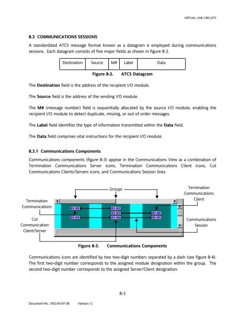
Communications components (figure 8-3) appear in the Communications View as a combination of<br />
Termination Communications Server icons, Termination Communications Client icons, Cut<br />
Communications Clients/Servers icons, and Communications Session lines.<br />
Termination<br />
Communications<br />
Cut<br />
Communication<br />
Client/Server<br />
Groups<br />
Figure 8-3. Communications Components<br />
Termination<br />
Communications<br />
Client<br />
Communications<br />
Session<br />
Communications icons are identified by two two-digit numbers separated by a dash (see figure 8-4).<br />
The first two-digit number corresponds to the assigned module designation within the group. The<br />
second two-digit number corresponds to the assigned Server/Client designation.