Voltage References
Voltage References
Voltage References
Create successful ePaper yourself
Turn your PDF publications into a flip-book with our unique Google optimized e-Paper software.
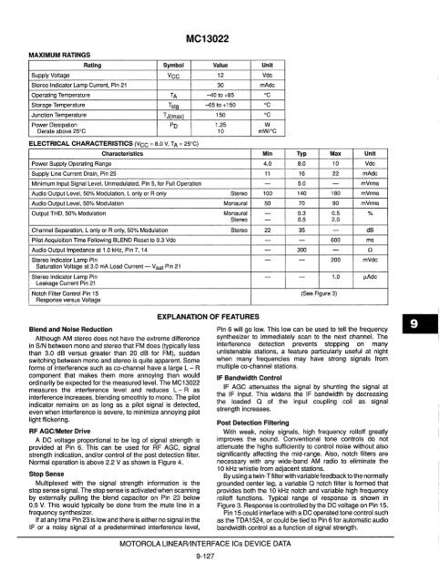
MAXIMUM RATINGS<br />
MC13022<br />
Rating Symbol Value Unit<br />
Supply <strong>Voltage</strong> VCC 12 Vdc<br />
Stereo Indicator lamp Current, Pin 21 30 mAdc<br />
Operating Temperature TA -40 to +65 DC<br />
Storage Temperature Tstg -65 to +150 °c<br />
Junction Temperature TJ(max) 150 °c<br />
Power Dissipation Po 1.25 W<br />
Derate above 25°C 10 mW/oC<br />
ELECTRICAL CHARACTERISTICS (VCC = 6.0 V, TA = 25DC)<br />
Characteristics Min Typ Max Unit<br />
Power Supply Operating Range 4.0 6.0 10 Vdc<br />
Supply line Current Drain, Pin 25 11 16 22 mAdc<br />
Minimum Input Signal level, Unmodulated, Pin 5, for Full Operation - 5.0 - mVrms<br />
Audio Output level, 50% Modulation, l only or R only Stereo 100 140 160 mVrms<br />
Audio Output level, 50% Modulation Monaural 50 70 90 mVrms<br />
Output THO, 50% Modulation Monaural - 0.3 0.5 %<br />
Stereo - 0.5 2.0<br />
Channel Separation, l only or R only, 50% Modulation Stereo 22 35 - dB<br />
Pilot Acquisition Time Following BLEND Reset to 0.3 Vdc - - 600 ms<br />
Audio Output Impedance at 1.0 kHz, Pin 7, 14 - 300 - (1<br />
Stereo Indicator lamp Pin - - 200 mVdc<br />
Saturation <strong>Voltage</strong> at 3.0 rnA load Current - V sat Pin 21<br />
Stereo Indicator lamp Pin - - 1.0 !lAdc<br />
leakage Current Pin 21<br />
Notch Filter Control Pin 15 (See Figure 3)<br />
Response versus <strong>Voltage</strong><br />
Blend and Noise Reduction<br />
Although AM stereo does not have the extreme difference<br />
in SIN between mono and stereo that FM does (typically less<br />
than 3.0 dB versus greater than 20 dB for FM), sudden<br />
switching between mono and stereo is quite apparent. Some<br />
forms of interference such as co-channel have a large L - R<br />
component that makes them more annoying than would<br />
ordinarily be expected for the measured level. The MC13022<br />
measures the interference level and reduces L - R as<br />
interference increases, blending smoothly to mono. The pilot<br />
indicator remains on as long as a pilot signal is detected,<br />
even when interference is severe, to minimize annoying pilot<br />
light flickering.<br />
RF AGC/Meter Drive<br />
A DC voltage proportional to be log of signal strength is<br />
provided at Pin 6. This can be used for RF AGe, signal<br />
strength indication, and/or control of the post detection filter.<br />
Normal operation is above 2.2 V as shown is Figure 4.<br />
Stop Sense<br />
Multiplexed with the signal strength information is the<br />
stop sense signal. The stop sense is activated when scanning<br />
by externally pulling the blend capacitor on Pin 23 below<br />
0.5 V. This would typically be done from the mute line in a<br />
frequency synthesizer.<br />
If at any time Pin 23 is low and there is either no signal in the<br />
IF or a noisy signal of a predetermined interference level,<br />
EXPLANATION OF FEATURES<br />
MOTOROLA LINEAR/INTERFACE ICs DEVICE DATA<br />
9-127<br />
Pin 6 will go low. This low can be used to tell the frequency<br />
synthesizer to immediately scan to the next channel. The<br />
interference detection prevents stopping on many<br />
un listenable stations, a feature particularly useful at night<br />
when many frequencies may have strong signals from<br />
multiple co-channel stations.<br />
IF Bandwidth Control<br />
IF AGC attenuates the signal by shunting the signal at<br />
the IF input. This widens the IF bandwidth by decreasing<br />
the loaded Q of the input coupling coil as signal<br />
strength increases.<br />
Post Detection Filtering<br />
With weak, noisy signals, high frequency rolloff greatly<br />
improves the sound. Conventional tone controls do not<br />
attenuate the highs sufficiently to control noise without also<br />
significantly affecting the mid-range. Also, notch filters are<br />
necessary with any wide-band AM radio to eliminate the<br />
10 kHz whistle from adjacent stations.<br />
By using a twin-Tfilterwith variable feedback to the normally<br />
grounded center leg, a variable Q notch filter is formed that<br />
provides both the 10kHz notch and variable high frequency<br />
rolloff functions. Typical range of response is shown in<br />
Figure 3. Response is controlled by the DC voltage on Pin 15.<br />
Pin 15 could interface with a DC operated tone control such<br />
as the TDA 1524, or could be tied to Pin 6 for automatic audio<br />
bandwidth control as a function of signal strength.


