

Voltage References
Voltage References
Voltage References

You also want an ePaper? Increase the reach of your titles
YUMPU automatically turns print PDFs into web optimized ePapers that Google loves.
PinNa. Name<br />
1, Video 1,<br />
3 Video 2<br />
2 ACC Filter<br />
4 Vert. Sync<br />
5, SCL,<br />
6 SDL<br />
7 Field ID<br />
8 Burst Gate<br />
9 Iref<br />
10 QuietGND<br />
11 PLL1 Filter<br />
12 PLL1 Filt.SW<br />
13 16 Fh/CSync<br />
14 Fh Ref<br />
15 15 k Return<br />
16 PLL2 Filter<br />
17 Ground<br />
18 ClkOut<br />
19 VCC3<br />
20,21,22 R,G, BOut<br />
23 VCC2<br />
24 Ground<br />
25 FastComm.<br />
26,27,28 B,G, R In<br />
29 Y21nput<br />
30, B-Y,<br />
31 R-Yln<br />
32 Y1 Clamp<br />
33 Y10ut<br />
34, SystemSel.,<br />
35 Sandcastle<br />
36, Xtal2,<br />
38 Xtal1<br />
37 N/C<br />
39 Ground<br />
40 VCC1<br />
41, B-Y,<br />
42 R-YOut<br />
43 Indent. Filter<br />
44 4FSC PLL<br />
MC44011<br />
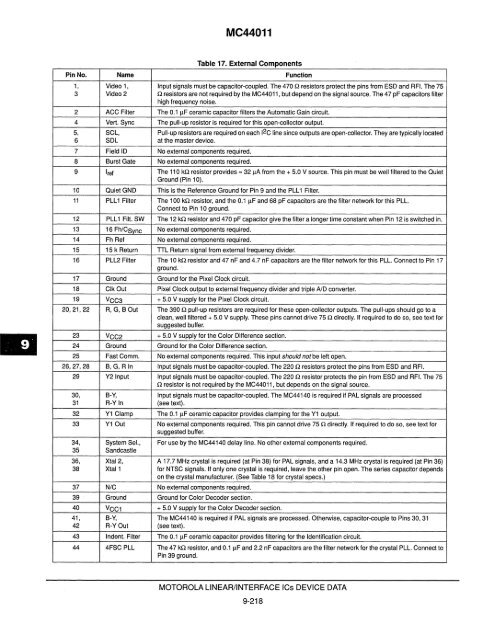
Table 17. External Components<br />
Function<br />
Input signals must be capacitor-coupled. The 470 Q resistors protect the pins from ESD and RFI. The 75<br />
Q resistors are not required by the MC44011, but depend on the signal source. The 47 pF capacitors filter<br />
high frequency noise.<br />
The 0.1 I1F ceramic capacitor filters the Automatic Gain circuit.<br />
The pull-up resistor is required for this open-collector output.<br />
Pull-up resistors are required on each 12C line since outputs are open-collector. They are typically located<br />
at the master device.<br />
No external components required.<br />
No external components required.<br />
The 110 kQ resistor provides = 3211A from the + 5.0 V source. This pin must be well filtered to the Quiet<br />
Ground (Pin 10).<br />
This is the Reference Ground for Pin 9 and the PLL 1 Filter.<br />
The 100 kQ resistor, and the 0.1 I1F and 68 pF capacitors are the filter network for this PLL.<br />
Connect to Pin 10 ground.<br />
The 12 kQ resistor and 470 pF capacitor give the filter a longer time constant when Pin 12 is switched in.<br />
No external components required.<br />
No external components required.<br />
TIL Return signal from external frequency divider.<br />
The 10 kQ resistor and 47 nF and 4.7 nF capacitors are the filter network for this PLL. Connect to Pin 17<br />
ground.<br />
Ground for the Pixel Clock circuit.<br />
Pixel Clock output to external frequency divider and triple ND converter.<br />
+ 5.0 V supply for the Pixel Clock circuit.<br />
The 390 Q pull-up resistors are required for these open-collector outputs. The pull-ups should go to a<br />
clean, well filtered + 5.0 V supply. These pins cannot drive 75 Q directly. If required to do so, see text for<br />
suggested buffer.<br />
+ 5.0 V supply for the Color Difference section.<br />
Ground for the Color Difference section.<br />
No external components required. This input should not be left open.<br />
Input signals must be capacitor-coupled. The 220 Q resistors protect the pins from ESD and RFI.<br />
Input signals must be capacitor-coupled. The 220 Q resistor protects the pin from ESD and RFI. The 75<br />
Q resistor is not required by the MC44011 , but depends on the signal source.<br />
Input signals must be capacitor-coupled. The MC44140 is required if PAL signals are processed<br />
(see text).<br />
The 0.1 I1F ceramic capacitor provides clamping for the Y1 output.<br />
No external components required. This pin cannot drive 75 Q directly. If required to do so, see text for<br />
suggested buffer.<br />
For use by the MC44140 delay line. No other external components required.<br />
A 17.7 MHz crystal is required (at Pin 38) for PAL signals, and a 14.3 MHz crystal is required (at Pin 36)<br />
for NTSC signals. If only one crystal is required, leave the other pin open. The series capacitor depends<br />
on the crystal manufacturer. (See Table 18 for crystal specs.)<br />
No external components required.<br />
Ground for Color Decoder section.<br />
+ 5.0 V supply for the Color Decoder section.<br />
The MC44140 is required if PAL signals are processed. Otherwise, capacitor-couple to Pins 30, 31<br />
(see text).<br />
The 0.1 I1F ceramic capacitor provides filtering for the Identification circuit.<br />
The 47 kQ resistor, and O.II1F and 2.2 nF capacitors are the filter network for the crystal PLL. Connect to<br />
Pin 39 ground.<br />
MOTOROLA LINEAR/INTERFACE ICs DEVICE DATA<br />
9-218


