

Voltage References
Voltage References
Voltage References

Create successful ePaper yourself
Turn your PDF publications into a flip-book with our unique Google optimized e-Paper software.
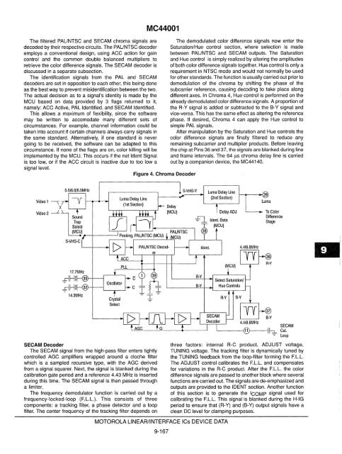
The filtered PAUNTSC and SECAM chroma signals are<br />
decoded by their respective circuits. The PAUNTSC decoder<br />
employs a conventional design, using ACC action for gain<br />
control and the common double balanced multipliers to<br />
retrieve the color difference signals. The SECAM decoder is<br />
discussed in a separate subsection.<br />
The identification signals from the PAL and SECAM<br />
decoders are set in opposition to each other, this being done<br />
as the best way to prevent misidentification between the two.<br />
The actual decision as to a signal's identity is made by the<br />
MCU based on data provided by 3 flags returned to it,<br />
namely: ACC Active, PAL Identified, and SECAM Identified.<br />
This allows a maximum of flexibility, since the software<br />
may be written to accomodate many different sets of<br />
circumstances. For example, channel information could be<br />
taken into account if certain channels always carry signals in<br />
the same standard. Alternatively, if one standard is never<br />
going to be received, the software can be adapted to this<br />
circumstance. If none of the flags are on, color killing will be<br />
implemented by the MCU. This occurs if the net Ident Signal<br />
is too low, or if the ACC circuit is inactive due to too Iowa<br />
signal level.<br />
Video 1 -.;:<br />
X<br />
Video 2 ---.L<br />
Crystal<br />
Select<br />
SECAM Decoder<br />
The SECAM signal from the high-pass filter enters tightly<br />
controlled AGC amplifiers wrapped around a cloche filter<br />
which is a sampled recursive type, with the AGC derived<br />
from a signal squarer. Next, the signal is blanked during the<br />
calibration gate period and a reference 4.43 MHz is inserted<br />
during this time. The SECAM signal is then passed through<br />
a limiter.<br />
The frequency demodulator function is carried out by a<br />
frequency-locked-loop (F.L.L.). This consists of three<br />
components: a tracking filter, a phase detector and a loop<br />
filter. The center frequency of the tracking filter depends on<br />
MC44001<br />
Figure 4. Chroma Decoder<br />
MOTOROLA LINEAR/INTERFACE ICs DEVICE DATA<br />
9-167<br />
The demodulated color difference signals now enter the<br />
Saturation/Hue control section, where selection is made<br />
between PAUNTSC and SECAM outputs. The Saturation<br />
and Hue control is simply realized by altering the amplitudes<br />
of both color difference signals together. Hue control is only a<br />
requirement in NTSC mode and would not normally be used<br />
for other standards. The function is usually carried out prior to<br />
demodulation of the chroma by shifting the phase of the<br />
subcarrier reference, causing decoding to take place along<br />
different axes. In Chroma 4, Hue control is performed on the<br />
already demodulated color difference signals. A proportion of<br />
the R-Y signal is added or subtracted to the B-Y signal and<br />
vice-versa. This has the same effect as altering the reference<br />
phase. If desired, Chroma 4 can apply the Hue control to<br />
simple PAL signals.<br />
After manipulation by the Saturation and Hue controls the<br />
color difference signals are finally filtered to reduce any<br />
remaining subcarrier and multiplier products. Before leaving<br />
the chip at Pins 36 and 37, the signals are blanked during line<br />
and frame intervals. The 64 Ils chroma delay line is carried<br />
out by a companion device, the MC44140.<br />
4.418.8MHz<br />
To Color<br />
Difference<br />
Stage<br />
SECAM<br />
Cal.<br />
Loop<br />
three factors: internal R-C product, ADJUST voltage,<br />
TUNING voltage. The tracking filter is dynamically tuned by<br />
the TUNING feedback from the loop-filter forming the F.L.L.<br />
The ADJUST control calibrates the F.L.L. and compensates<br />
for variations in the R-C product. After the F.L.L. the color<br />
difference Signals are passed to another block where several<br />
functions are carried out. The signals are de-emphasized and<br />
outputs are provided to the IDENT section. Another function<br />
of this section is to generate the ICOMP signal used for<br />
calibrating the F.L.L. This signal is blanked during the H-IG<br />
period to ensure that (R-Y) and (B-Y) output signals have a<br />
clean DC level for clamping purposes.


