

Voltage References
Voltage References
Voltage References

You also want an ePaper? Increase the reach of your titles
YUMPU automatically turns print PDFs into web optimized ePapers that Google loves.
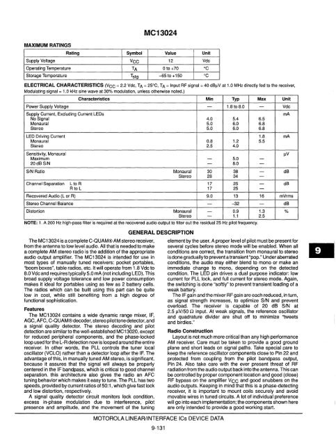
MAXIMUM RATINGS<br />
MC13024<br />
Rating Symbol Value Unit<br />
Supply <strong>Voltage</strong> VCC 12 Vdc<br />
Operating Temperature TA o to +70 °c<br />
Storage Temperature Tstg -65 to +150 °C<br />
ELECTRICAL CHARACTERISTICS (VCC = 2.2 Vdc, TA = 25°C, TA = Input RF signal = 40 dBIlV at 1.0 MHz directly fed to the receiver,<br />
Modulating signal = 1.0 kHz sine wave at 30% modulation, unless otherwise noted.)<br />
Characteristics Min Typ Max Unit<br />
Power Supply <strong>Voltage</strong> - 1.8 to 8.0 - Vdc<br />
Supply Current, Excluding Current LEDs rnA<br />
No Signal 4.0 5.4 6.5<br />
Monaural 5.0 6.0 6.8<br />
Stereo 5.0 6.0 6.8<br />
LED Driving Current 1.8 rnA<br />
Monaural 0.8 1.2 5.5<br />
Stereo 2.5 4.0<br />
Sensitivity, Monaural IlV<br />
Maximum - 5.0 -<br />
20dBS/N - 8.0 -<br />
SIN Ratio Monaural 30 38 - dB<br />
Stereo 28 34 -<br />
Channel Separation LtoR 17 25 - dB<br />
Rto L 17 25 -<br />
Recovered Audio (L or R) 9.0 13 16 mVrms<br />
Stereo Channel Balance - --32 - dB<br />
Distortion Monaural - 0.9 1.3 %<br />
Stereo - 1.1 2.5<br />
NOTE: 1. A 200 Hz high-pass filter IS reqUired at the recovered audio output to filter out the reSidual 25 Hz pilot frequency.<br />
The MC 13024 is a complete C-QUAM® AM stereo receiver,<br />
from the antenna to low level audio. All that is needed to make<br />
a complete AM stereo radio is the addition of the appropriate<br />
audio output amplifier. The MC13024 is intended for use in<br />
most types of manually tuned receivers: pocket portables,<br />
"boom boxes", table radios, etc. It will operate from 1.8 Vdc to<br />
8.0 Vdc and requires typically 5.0 mA (not including LED). This<br />
broad supply voltage tolerance and low power consumption<br />
makes it ideal for portables using as few as 2 battery cells.<br />
The radios which can be built using this part can be quite<br />
low in cost, while still benefiting from a high degree of<br />
functional sophistication.<br />
Features<br />
The MC13024 contains a wide dynamic range mixer, IF,<br />
AGC, AFC, C-QUAM® decoder, stereo pilotlone detector, and<br />
a signal quality detector. The stereo decoding and pilot<br />
detection are similar to the well-established MC13020, except<br />
for reduced peripheral components, and the phase-locked<br />
loop used forthe L-R detection now is looped around the entire<br />
receiver. In other words, the PLL controls the tuner local<br />
oscillator (VCLO) rather than a detector loop after the IF. The<br />
advantage of this, in manually tuned AM stereo, is significant,<br />
because it assures that the signal will always be properly<br />
centered in the IF bandpass, which is critical to good channel<br />
separation. this architecture also gives the radio an AFC<br />
tuning behavior which makes it easy to tune. The PLL has two<br />
speeds, provided by current ratios of 50:1, which give fast lock<br />
and low distortion, respectively.<br />
A signal quality detector circuit monitors lock condition,<br />
excess in-phase modulation due to interference, pilot<br />
presence and amplitude, and the movement of the tuning<br />
GENERAL DESCRIPTION<br />
MOTOROLA LINEAR/INTERFACE ICs DEVICE DATA<br />
9-131<br />
element by the user. A proper level of pilot must be present for<br />
several cycles before stereo mode will be enabled. When all<br />
conditions are correct, the transition from monaural to stereo<br />
is done gradually to prevent a transient "pop." Under aberrated<br />
conditions, the audio may either blend to mono or make an<br />
immediate change to mono, depending on the detected<br />
condition. The LED pin drives a dual purpose indicator: low<br />
current for PLL lock, and full current for stereo mode. Again,<br />
the switching is done "softly" to prevent transient loading of a<br />
weak battery.<br />
The I F gain and the mixer RF gain are each reduced, in turn,<br />
as signal strength increases, to optimize SIN and prevent<br />
overload. The receiver is capable of 20 dB SIN at<br />
2.5!iV/50 Q input. At weak signals, the reference oscillator<br />
and quadrature divider are shut off to minimize '1weets<br />
and birdies."<br />
Radio Construction<br />
Layout is not much more critical than any high performance<br />
AM receiver. Care must be taken to provide a good ground<br />
plane and short leads on Signal paths. Take special care to<br />
keep the reference oscillator components close to Pin 22 and<br />
protected from coupling from the pilot bandpass output,<br />
Pin 24. Also take care with the ever present threat of RF<br />
radiation from the audio output back into the antenna. This can<br />
be controlled by proper component location and good (close)<br />
RF bypass on the amplifier VCC and good snubbers on the<br />
audio outputs. Keeping in mind that this is a phase-detecting<br />
receiver, it is important to mount coils securely and avoid<br />
movable wires in tuned circuits. A lot of individual preference<br />
will go into each implementation; the components shown here<br />
are only intended to provide a good working start.


