

CV7300 Instruction Manual - TECO-Westinghouse Motor Company
CV7300 Instruction Manual - TECO-Westinghouse Motor Company
CV7300 Instruction Manual - TECO-Westinghouse Motor Company

Create successful ePaper yourself
Turn your PDF publications into a flip-book with our unique Google optimized e-Paper software.
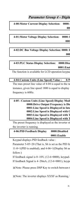
Parameter Group 4 - Digital Display Operation Mode<br />
4-00:<strong>Motor</strong> Current Display Selection: 0000: Disable <strong>Motor</strong> Current Display<br />
0001: Enable <strong>Motor</strong> Current Display<br />
4-01:<strong>Motor</strong> Voltage Display Selection: 0000: Disable <strong>Motor</strong> Voltage Display<br />
0001: Enable <strong>Motor</strong> Voltage Display<br />
4-02:DC Bus Voltage Display Selection: 0000: Disable Bus Voltage Display<br />
0001: Enable Bus Voltage Display<br />
4-03:PLC Status Display Selection: 0000:Disable PLC Status Display<br />
0001:Enable PLC Status Display<br />
The function is available for LCD operation keypad, but not for LED one.<br />
4-33<br />
Chapter 4 Software Index<br />
4-04:Custom Units (Line Speed) Value : 0-9999<br />
The max preset line value of 4-04 is equal to the rated frequency (0-05) of the motor. For<br />
instance, given line speed 1800 is equal to display 900 when output is 30Hz while the operation<br />
frequency is 60Hz.<br />
4-05 : Custom Units (Line Speed) Display Mode<br />
0000:Drive Output Frequency is Displayed<br />
0001:Line Speed is Displayed in Integer (xxxx)<br />
0002:Line Speed is Displayed with One Decimal Place (xxx.x)<br />
0003:Line Speed is Displayed with Two Decimal Places (xx.xx)<br />
0004:Line Speed is Displayed with Three Decimal Places (x.xxx)<br />
The preset frequency is displayed as the inverter stops while the operation line speed is displayed as<br />
the inverter is running.<br />
4-06:PID Feedback Display 0000:Disabled<br />
0001:Enable<br />
Keypad displays PID feedback value :<br />
Parameter 5-05=20 (That is, S6 is set as the PID feedback analog terminal, refer to PID),<br />
11-0=1(PID is enabled), and 4-06=1(Display S6 as PID analog feedback value 0~100, the formula as<br />
follow:)<br />
If feedback signal is 0~10V, (12-6=0000), keypad display value = (S6/10V)*100<br />
If feedback Signal is 4~20mA, (12-6=0001), keypad display value = (S6/20mA)*100<br />
※Note: Please press DSP Key to switch between the output frequency and PID feedback value.<br />
※Note: The inverter displays XXXF as Running, while XXXr as Stop.


