

CV7300 Instruction Manual - TECO-Westinghouse Motor Company
CV7300 Instruction Manual - TECO-Westinghouse Motor Company
CV7300 Instruction Manual - TECO-Westinghouse Motor Company

You also want an ePaper? Increase the reach of your titles
YUMPU automatically turns print PDFs into web optimized ePapers that Google loves.
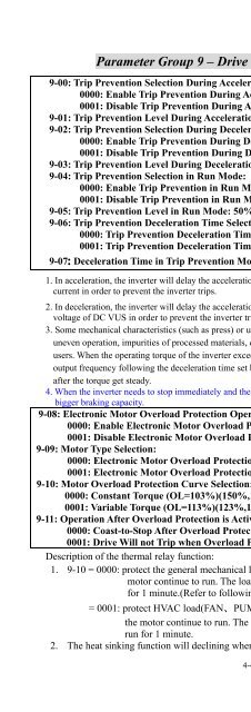
Parameter Group 9 – Drive and Load Protection Modes<br />
9-00: Trip Prevention Selection During Acceleration:<br />
0000: Enable Trip Prevention During Acceleration<br />
0001: Disable Trip Prevention During Acceleration<br />
9-01: Trip Prevention Level During Acceleration: 50% ~ 300%<br />
9-02: Trip Prevention Selection During Deceleration:<br />
0000: Enable Trip Prevention During Deceleration<br />
0001: Disable Trip Prevention During Deceleration<br />
9-03: Trip Prevention Level During Deceleration: 50% ~ 300%<br />
9-04: Trip Prevention Selection in Run Mode:<br />
0000: Enable Trip Prevention in Run Mode<br />
0001: Disable Trip Prevention in Run Mode<br />
9-05: Trip Prevention Level in Run Mode: 50% ~ 300%<br />
9-06: Trip Prevention Deceleration Time Selection in Run Mode:<br />
0000: Trip Prevention Deceleration Time Set by 3-03<br />
0001: Trip Prevention Deceleration Time Set by 9-07<br />
9-07: Deceleration Time in Trip Prevention Mode (sec): 0.1 ~ 3600.0<br />
4-48<br />
Chapter 4 Software Index<br />
1. In acceleration, the inverter will delay the acceleration time if the time is too short resulting in the over<br />
current in order to prevent the inverter trips.<br />
2. In deceleration, the inverter will delay the acceleration time if the time is too short resulting in the over<br />
voltage of DC VUS in order to prevent the inverter trips with ‘OV’ displayed.<br />
3. Some mechanical characteristics (such as press) or unusual breakdown (seize due to insufficient lubrication,<br />
uneven operation, impurities of processed materials, etc.) will cause the inverter to trip, thus inconvenience<br />
users. When the operating torque of the inverter exceeds the setting of 9-05, the inverter will lower the<br />
output frequency following the deceleration time set by 9-06, and return to the normal operation frequency<br />
after the torque get steady.<br />
4. When the inverter needs to stop immediately and the braking resistor is connected, set 9-02 to 1 to get<br />
bigger braking capacity.<br />
9-08: Electronic <strong>Motor</strong> Overload Protection Operation Mode:<br />
0000: Enable Electronic <strong>Motor</strong> Overload Protection<br />
0001: Disable Electronic <strong>Motor</strong> Overload Protection<br />
9-09: <strong>Motor</strong> Type Selection:<br />
0000: Electronic <strong>Motor</strong> Overload Protection Set for Non-Inverter Duty <strong>Motor</strong><br />
0001: Electronic <strong>Motor</strong> Overload Protection Set for Inverter Duty <strong>Motor</strong><br />
9-10: <strong>Motor</strong> Overload Protection Curve Selection:<br />
0000: Constant Torque (OL=103%)(150%,1 minute)<br />
0001: Variable Torque (OL=113%)(123%,1 minute)<br />
9-11: Operation After Overload Protection is Activated:<br />
0000: Coast-to-Stop After Overload Protection is Activated<br />
0001: Drive Will not Trip when Overload Protection is Activated (OL1)<br />
Description of the thermal relay function:<br />
1. 9-10 = 0000: protect the general mechanical load, the load is less than 103% rated current, the<br />
motor continue to run. The load is larger than 150% rated current, the motor will run<br />
for 1 minute.(Refer to following curve(1).<br />
= 0001: protect HVAC load(FAN、PUMP…so on): the load is less than 113% rated current,<br />
the motor continue to run. The load is larger than 123% rated current, the motor will<br />
run for 1 minute.<br />
2. The heat sinking function will declining when the motor run at low speed. So the thermal relay


