Alternative Support Systems for Cantilever - National Transportation ...
Alternative Support Systems for Cantilever - National Transportation ...
Alternative Support Systems for Cantilever - National Transportation ...
You also want an ePaper? Increase the reach of your titles
YUMPU automatically turns print PDFs into web optimized ePapers that Google loves.
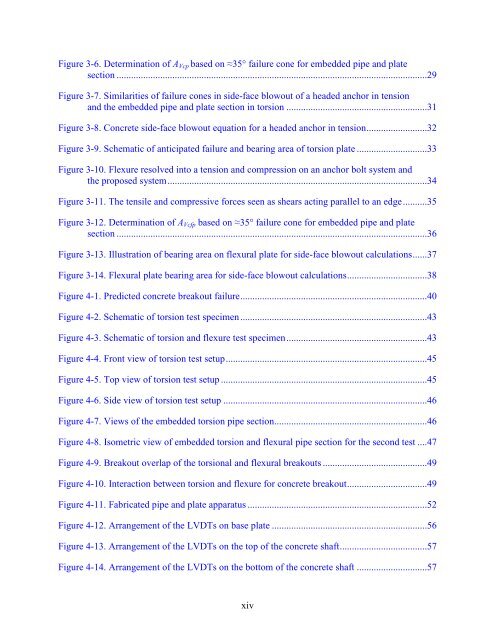
Figure 3-6. Determination of AVcp based on ≈35° failure cone <strong>for</strong> embedded pipe and plate<br />
section ................................................................................................................................29<br />
Figure 3-7. Similarities of failure cones in side-face blowout of a headed anchor in tension<br />
and the embedded pipe and plate section in torsion ..........................................................31<br />
Figure 3-8. Concrete side-face blowout equation <strong>for</strong> a headed anchor in tension .........................32<br />
Figure 3-9. Schematic of anticipated failure and bearing area of torsion plate .............................33<br />
Figure 3-10. Flexure resolved into a tension and compression on an anchor bolt system and<br />
the proposed system ...........................................................................................................34<br />
Figure 3-11. The tensile and compressive <strong>for</strong>ces seen as shears acting parallel to an edge ..........35<br />
Figure 3-12. Determination of AVcfp based on ≈35° failure cone <strong>for</strong> embedded pipe and plate<br />
section ................................................................................................................................36<br />
Figure 3-13. Illustration of bearing area on flexural plate <strong>for</strong> side-face blowout calculations ......37<br />
Figure 3-14. Flexural plate bearing area <strong>for</strong> side-face blowout calculations .................................38<br />
Figure 4-1. Predicted concrete breakout failure .............................................................................40<br />
Figure 4-2. Schematic of torsion test specimen .............................................................................43<br />
Figure 4-3. Schematic of torsion and flexure test specimen ..........................................................43<br />
Figure 4-4. Front view of torsion test setup ...................................................................................45<br />
Figure 4-5. Top view of torsion test setup .....................................................................................45<br />
Figure 4-6. Side view of torsion test setup ....................................................................................46<br />
Figure 4-7. Views of the embedded torsion pipe section ...............................................................46<br />
Figure 4-8. Isometric view of embedded torsion and flexural pipe section <strong>for</strong> the second test ....47<br />
Figure 4-9. Breakout overlap of the torsional and flexural breakouts ...........................................49<br />
Figure 4-10. Interaction between torsion and flexure <strong>for</strong> concrete breakout .................................49<br />
Figure 4-11. Fabricated pipe and plate apparatus ..........................................................................52<br />
Figure 4-12. Arrangement of the LVDTs on base plate ................................................................56<br />
Figure 4-13. Arrangement of the LVDTs on the top of the concrete shaft ....................................57<br />
Figure 4-14. Arrangement of the LVDTs on the bottom of the concrete shaft .............................57<br />
xiv


