Alternative Support Systems for Cantilever - National Transportation ...
Alternative Support Systems for Cantilever - National Transportation ...
Alternative Support Systems for Cantilever - National Transportation ...
Create successful ePaper yourself
Turn your PDF publications into a flip-book with our unique Google optimized e-Paper software.
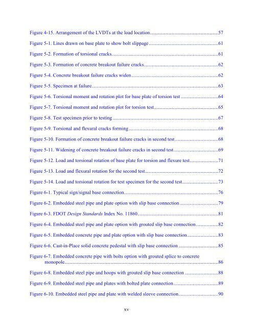
Figure 4-15. Arrangement of the LVDTs at the load location .......................................................57<br />
Figure 5-1. Lines drawn on base plate to show bolt slippage ........................................................61<br />
Figure 5-2. Formation of torsional cracks ......................................................................................61<br />
Figure 5-3. Formation of concrete breakout failure cracks ............................................................62<br />
Figure 5-4. Concrete breakout failure cracks widen ......................................................................62<br />
Figure 5-5. Specimen at failure ......................................................................................................63<br />
Figure 5-6. Torsional moment and rotation plot <strong>for</strong> base plate of torsion test ..............................64<br />
Figure 5-7. Torsional moment and rotation plot <strong>for</strong> torsion test ....................................................65<br />
Figure 5-8. Test specimen prior to testing .....................................................................................67<br />
Figure 5-9. Torsional and flexural cracks <strong>for</strong>ming ........................................................................68<br />
Figure 5-10. Formation of concrete breakout failure cracks in second test ...................................68<br />
Figure 5-11. Widening of concrete breakout failure cracks in second test ....................................69<br />
Figure 5-12. Load and torsional rotation of base plate <strong>for</strong> torsion and flexure test .......................71<br />
Figure 5-13. Load and flexural rotation <strong>for</strong> the second test ...........................................................72<br />
Figure 5-14. Load and torsional rotation <strong>for</strong> test specimen <strong>for</strong> the second test .............................73<br />
Figure 6-1. Typical sign/signal base connection ............................................................................76<br />
Figure 6-2. Embedded steel pipe and plate option with slip base connection ...............................79<br />
Figure 6-3. FDOT Design Standards Index No. 11860 .................................................................81<br />
Figure 6-4. Embedded steel pipe and plate option with grouted slip base connection ..................82<br />
Figure 6-5. Embedded concrete pipe and plate option with slip base connection .........................83<br />
Figure 6-6. Cast-in-Place solid concrete pedestal with slip base connection ................................85<br />
Figure 6-7. Embedded concrete pipe with bolts option with grouted splice to concrete<br />
monopole............................................................................................................................86<br />
Figure 6-8. Embedded steel pipe and hoops with grouted slip base connection ...........................88<br />
Figure 6-9. Embedded steel pipe and plates with bolted plate connection ....................................89<br />
Figure 6-10. Embedded steel pipe and plate with welded sleeve connection ................................90<br />
xv


