Alternative Support Systems for Cantilever - National Transportation ...
Alternative Support Systems for Cantilever - National Transportation ...
Alternative Support Systems for Cantilever - National Transportation ...

Create successful ePaper yourself
Turn your PDF publications into a flip-book with our unique Google optimized e-Paper software.
3.2.2 Equivalent Side-Face Blowout Strength<br />
The other method to determine the flexural strength of the embedded pipe and plate section<br />
is to determine the available side-face blowout strength of concrete <strong>for</strong> the embedded pipe and<br />
plate section. The side-face blowout strength was expected to be calculated similarly to the side-<br />
face blowout strength of a headed anchor in tension, with the bearing area modified from the<br />
head of the anchor to the bearing area of the flexural plate.<br />
The similarity in these failures shows that there requires little manipulation of the equation<br />
to determine the side-face blowout strength <strong>for</strong> the embedded pipe and plate section. Equation 3-<br />
8 seen earlier in the chapter describes the nominal side-face blowout strength of a headed anchor<br />
in tension while Equation 3-9 describes the mean side-face blowout strength of a headed anchor<br />
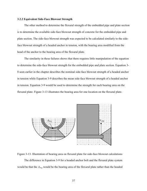
in tension. Equation 3-9 would be used to determine the strength <strong>for</strong> each bearing area on the<br />
flexural plate. Figure 3-13 illustrates the bearing area <strong>for</strong> one location on the flexural plate.<br />
Abrg<br />
Figure 3-13. Illustration of bearing area on flexural plate <strong>for</strong> side-face blowout calculations<br />
The difference in Equation 3-9 <strong>for</strong> a headed anchor bolt and the flexural plate system<br />
would be that the Abrg would be the bearing area of the flexural plate rather than the headed<br />
37<br />
Nsbfp