Alternative Support Systems for Cantilever - National Transportation ...
Alternative Support Systems for Cantilever - National Transportation ...
Alternative Support Systems for Cantilever - National Transportation ...

You also want an ePaper? Increase the reach of your titles
YUMPU automatically turns print PDFs into web optimized ePapers that Google loves.
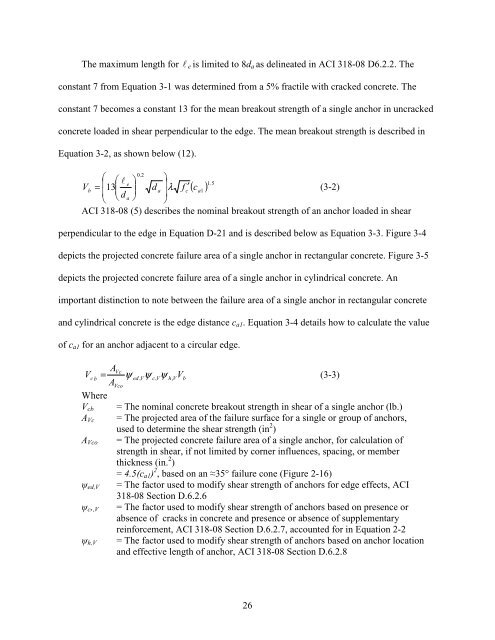
The maximum length <strong>for</strong> le is limited to 8da as delineated in ACI 318-08 D6.2.2. The<br />
constant 7 from Equation 3-1 was determined from a 5% fractile with cracked concrete. The<br />
constant 7 becomes a constant 13 <strong>for</strong> the mean breakout strength of a single anchor in uncracked<br />
concrete loaded in shear perpendicular to the edge. The mean breakout strength is described in<br />
Equation 3-2, as shown below (12).<br />
( ) 5 . 1<br />
0.<br />
2 ⎛<br />
e<br />
V ⎜ ⎛ l ⎞<br />
b = 13<br />
⎜ ⎜<br />
d ⎟<br />
a ⎝ ⎝ ⎠<br />
⎞<br />
d ⎟<br />
a λ<br />
⎟<br />
⎠<br />
f ′ c ca1<br />
(3-2)<br />
ACI 318-08 (5) describes the nominal breakout strength of an anchor loaded in shear<br />
perpendicular to the edge in Equation D-21 and is described below as Equation 3-3. Figure 3-4<br />
depicts the projected concrete failure area of a single anchor in rectangular concrete. Figure 3-5<br />
depicts the projected concrete failure area of a single anchor in cylindrical concrete. An<br />
important distinction to note between the failure area of a single anchor in rectangular concrete<br />
and cylindrical concrete is the edge distance ca1. Equation 3-4 details how to calculate the value<br />
of ca1 <strong>for</strong> an anchor adjacent to a circular edge.<br />
A<br />
= ψ ψ ψ V<br />
(3-3)<br />
Vc<br />
V c b<br />
ed , V c,<br />
V h,<br />
V<br />
AVco<br />
Where<br />
Vcb<br />
AVc<br />
AVco<br />
ψed,V<br />
ψc,,V<br />
ψh,V<br />
b<br />
= The nominal concrete breakout strength in shear of a single anchor (lb.)<br />
= The projected area of the failure surface <strong>for</strong> a single or group of anchors,<br />
used to determine the shear strength (in 2 )<br />
= The projected concrete failure area of a single anchor, <strong>for</strong> calculation of<br />
strength in shear, if not limited by corner influences, spacing, or member<br />
thickness (in. 2 )<br />
= 4.5(ca1) 2 , based on an ≈35° failure cone (Figure 2-16)<br />
= The factor used to modify shear strength of anchors <strong>for</strong> edge effects, ACI<br />
318-08 Section D.6.2.6<br />
= The factor used to modify shear strength of anchors based on presence or<br />
absence of cracks in concrete and presence or absence of supplementary<br />
rein<strong>for</strong>cement, ACI 318-08 Section D.6.2.7, accounted <strong>for</strong> in Equation 2-2<br />
= The factor used to modify shear strength of anchors based on anchor location<br />
and effective length of anchor, ACI 318-08 Section D.6.2.8<br />
26