- Page 1 and 2:
Report No. BDK75 977-04 Date: Augus
- Page 3 and 4:
Metric Conversion Table SYMBOL WHEN
- Page 5 and 6:
ALTERNATIVE SUPPORT SYSTEMS FOR CAN
- Page 7 and 8:
EXECUTIVE SUMMARY During the 2004 h
- Page 9 and 10:
CHAPTER TABLE OF CONTENTS 1 INTRODU
- Page 11 and 12:
Torsion Test Data .................
- Page 13 and 14:
LIST OF FIGURES Figure page Figure
- Page 15 and 16:
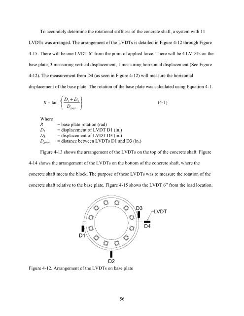
Figure 4-15. Arrangement of the LVD
- Page 17 and 18:
CHAPTER 1 INTRODUCTION This project
- Page 19 and 20:
CHAPTER 2 BACKGROUND The following
- Page 21 and 22: information obtained in the late 19
- Page 23 and 24: these problems. The concern with fa
- Page 25 and 26: opposite side, see Figure 2-2 The s
- Page 27 and 28: 2.2.4 Helical Pipes This option wou
- Page 29 and 30: 2.3 Alternative Foundations from Ot
- Page 31 and 32: Figure 2-10. Drilled concrete piles
- Page 33 and 34: Figure 2-13. Grouted soil anchors G
- Page 35 and 36: The pad and pier foundation, found
- Page 37 and 38: comments and recommendations on pre
- Page 39 and 40: CHAPTER 3 DESIGN IMPLICATIONS Based
- Page 41 and 42: Figure 3-2. Differences between con
- Page 43 and 44: 2 [ ] 2 2 ( r ) + 3. 25 ( r ) − (
- Page 45 and 46: eakout surface for a single plate,
- Page 47 and 48: strength of a headed anchor in tens
- Page 49 and 50: Figure 3-9. Schematic of anticipate
- Page 51 and 52: Vbfp l e tfp bfp f’c ca1 = the ba
- Page 53 and 54: 3.2.2 Equivalent Side-Face Blowout
- Page 55 and 56: computed. See Equation 3-14 below t
- Page 57 and 58: One method to quantify the failure
- Page 59 and 60: • An additional 12-4.5” long, 1
- Page 61 and 62: Applied load Lever arm Figure 4-4.
- Page 63 and 64: Figure 4-8. Isometric view of embed
- Page 65 and 66: Flexural plate breakout area Torsio
- Page 67 and 68: 4.2.4 Annular Base Plate Design The
- Page 69 and 70: torsional strength of the lever arm
- Page 71: 4.4 Concrete Block and Tie-Down Des
- Page 75 and 76: 4.7 Summary of Torsion and Flexure
- Page 77 and 78: foundation displayed the predicted
- Page 79 and 80: Figure 5-5. Specimen at failure 5.1
- Page 81 and 82: Figure 5-7. Torsional moment and ro
- Page 83 and 84: torsional 45 degree crack formation
- Page 85 and 86: Figure 5-11. Widening of concrete b
- Page 87 and 88: Failure cracks widen Bond loosens F
- Page 89 and 90: Rear of shaft Figure 5-14. Load and
- Page 91 and 92: testing, signifying that the predic
- Page 93 and 94: provided in NCHRP Report 412 were i
- Page 95 and 96: 6.2.2 Tapered Embedded Steel Pipe a
- Page 97 and 98: Figure 6-3. FDOT Design Standards I
- Page 99 and 100: This option provides a possible alt
- Page 101 and 102: 6.2.5 Cast-in-Place Solid Concrete
- Page 103 and 104: This option does have some disadvan
- Page 105 and 106: Figure 6-9. Embedded steel pipe and
- Page 107 and 108: However, the fillet welds are susce
- Page 109 and 110: APPENDIX A TEST APPARATUS DRAWINGS
- Page 111 and 112: Figure A-3. Dimensioned side elevat
- Page 113 and 114: Figure A-5. Dimensioned drawings of
- Page 115 and 116: Figure A-7. Dimensioned plan drawin
- Page 117 and 118: Figure A-9. Dimensioned drawing of
- Page 119 and 120: Figure A-11. Dimensioned view of em
- Page 121 and 122: STIFFENER DESIGN Calculation of Cap
- Page 123 and 124:
L breakout Concrete Breakout Equiva
- Page 125 and 126:
Abrg L⋅b 7 in 2 := = .5 Nsb 200
- Page 127 and 128:
β 1 f c Calculations Using ACI Str
- Page 129 and 130:
Determine Flexural Capacity of Roun
- Page 131 and 132:
DEVELOPMENT LENGTHS OF FLEXURAL REI
- Page 133 and 134:
Short Pipe Design Flexural Strength
- Page 135 and 136:
Long Pipe Design Flexural Strength
- Page 137 and 138:
Superstructure Assembly Strength -
- Page 139 and 140:
Weld Design Tn_blowout Vweld := Tor
- Page 141 and 142:
Check_Bolt_Shear := "Sufficient Str
- Page 143 and 144:
Check Reinforcement No_Bars_Block_R
- Page 145 and 146:
Tie-Down Design Block Properties Wi
- Page 147 and 148:
Vmax Total Load that the Tie-down m
- Page 149 and 150:
λpf := .38⋅ λpw := 3.76⋅ E F
- Page 151 and 152:
Input and Properties Shaft Torsion
- Page 153 and 154:
ψcV := 1.4 ψecV := 1.0 ψedV := 1
- Page 155 and 156:
lbreakout := L + 2⋅1.5ca1 lbreako
- Page 157 and 158:
Rn_weld := Throat⋅FW Rn_weld 11.1
- Page 159 and 160:
⎛ ⎜ ⎜⎜⎜⎜⎜⎜⎜ 9.250
- Page 161 and 162:
Flexural Capacity of T-Plates Using
- Page 163 and 164:
FAILURE EQUATIONS Torsion Threshold
- Page 165 and 166:
Required Length of Shaft Based on B
- Page 167 and 168:
Design Axial Strength ϕcomp := .90
- Page 169 and 170:
Design Axial Strength ϕcomp := .90
- Page 171 and 172:
Zp := ⎛ ⎜ ⎝ bp tp⋅ 2 ⎞
- Page 173 and 174:
Bolt Properties - D1" ASTM A325 Cen
- Page 175 and 176:
CONCRETE BLOCK Concrete Block Desig
- Page 177 and 178:
Check Shear Check_Shear_B := "Suffi
- Page 179 and 180:
7'-4" 8" 5'-4" 8" 1'-3" Calculate s
- Page 181 and 182:
Required Capacity of the Channel As
- Page 183 and 184:
Check_Flange_Compact_Unit := "Compa
- Page 185 and 186:
Rear of Shaft Face of Shaft Figure
- Page 187 and 188:
Bolt slippage ends Predicted failur
- Page 189 and 190:
APPENDIX D DESIGN GUIDELINES For th
- Page 191 and 192:
The designer should then use this i
- Page 193 and 194:
• Determine the angle required fo
- Page 195 and 196:
Superstructure Base Connection Foun
- Page 197 and 198:
1.5ca1 1.5ca1 Length of bearing are
- Page 199 and 200:
Vu = 9.04 kip T .u = 198.88 ft·kip
- Page 201 and 202:
Increase threaded rod diameter to 2
- Page 203 and 204:
Embedded Pipe and Torsion Plates De
- Page 205 and 206:
⎝ ⎠ Check_Breakout_Torsion := "
- Page 207 and 208:
Lbreakout := tflex.plate + 2⋅1.5c
- Page 209 and 210:
( ) .85 if fc < 4000psi β 1 f c .6
- Page 211 and 212:
REFERENCES 1. Cook, R.A., and Halco