Analysis of the extended defects in 3C-SiC.pdf - Nelson Mandela ...
Analysis of the extended defects in 3C-SiC.pdf - Nelson Mandela ...
Analysis of the extended defects in 3C-SiC.pdf - Nelson Mandela ...

You also want an ePaper? Increase the reach of your titles
YUMPU automatically turns print PDFs into web optimized ePapers that Google loves.
48<br />
associated displacement field <strong>of</strong> <strong>the</strong> stack<strong>in</strong>g fault to obta<strong>in</strong> a l<strong>in</strong>e <strong>in</strong>tensity pr<strong>of</strong>ile <strong>of</strong><br />
<strong>the</strong> fr<strong>in</strong>ges.<br />
As discussed <strong>in</strong> Section 2.6 stack<strong>in</strong>g faults are produced by a disruption <strong>of</strong> <strong>the</strong> regular<br />
stack<strong>in</strong>g sequence <strong>of</strong> a material. It can also be seen as two regions <strong>of</strong> <strong>the</strong> crystal<br />
hav<strong>in</strong>g been shifted relative to one ano<strong>the</strong>r by a distance given by a displacement<br />
vector R which may be a non-lattice translation as shown by Fig. 4.4. The<br />
displacement vector has a component parallel to <strong>the</strong> fault plane R|| and normal to it<br />
R . Thus <strong>the</strong> presence <strong>of</strong> this fault will <strong>in</strong>troduce a phase shift α = 2πg·R which<br />
modifies <strong>the</strong> solution to <strong>the</strong> DHW equations for <strong>the</strong> bottom section (section II) <strong>of</strong> <strong>the</strong><br />
crystal. If α is an <strong>in</strong>teger multiple <strong>of</strong> π no defect contrast will be seen which shows<br />
that R is a lattice translation vector and effectively no modification <strong>of</strong> <strong>the</strong> solutions to<br />
<strong>the</strong> DHW equations result. If R is a non-lattice translation, α is not an <strong>in</strong>teger multiple<br />
<strong>of</strong> π and image contrast <strong>of</strong> <strong>the</strong> form <strong>of</strong> alternat<strong>in</strong>g light and dark fr<strong>in</strong>ges will be<br />
formed.<br />
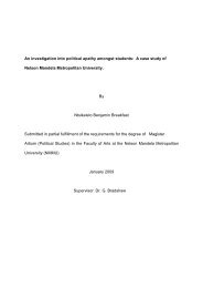
Fig. 4.4. (a) Schematic illustration <strong>of</strong> a planar defect separat<strong>in</strong>g crystal sections I<br />
and II; (b) <strong>in</strong>cl<strong>in</strong>ed planar defect comb<strong>in</strong>ed with <strong>the</strong> column approximation (from De<br />
Graef (2003))<br />
To simulate such an <strong>in</strong>tensity pr<strong>of</strong>ile <strong>the</strong> follow<strong>in</strong>g procedure is used. Consider a<br />
crystal with thickness z0 conta<strong>in</strong><strong>in</strong>g a stack<strong>in</strong>g fault as shown <strong>in</strong> Fig. 4.4 (b). Region 1<br />
has been shifted with respect to region II by a vector R. The top section <strong>of</strong> <strong>the</strong> crystal<br />
(region 1) is defect free and is described by a scatter<strong>in</strong>g matrix Sscat(s1.z1) where z1 is<br />
<strong>the</strong> distance from <strong>the</strong> top surface to <strong>the</strong> fault. The bottom section is shifted with<br />
respect to <strong>the</strong> top and is described by a different scatter<strong>in</strong>g matrix M(s2.z2) s<strong>in</strong>ce it lies<br />
<strong>in</strong> a different orientation with respect to <strong>the</strong> top. The two scatter<strong>in</strong>g matrices are as<br />
follows,