

Perkins L4 Workshop Manual - L-36 Fleet
Perkins L4 Workshop Manual - L-36 Fleet
Perkins L4 Workshop Manual - L-36 Fleet

You also want an ePaper? Increase the reach of your titles
YUMPU automatically turns print PDFs into web optimized ePapers that Google loves.
1<br />
(J'<br />
J.<br />
CYLINDER HEAO<br />
The Diesel engine rarely, if ever, needs the<br />
periodical decarbonising that is accepted as a<br />
matter of course with the petrol engine, insofar<br />
that in an engine operating on the diesel cycle,<br />
carbon, beyond a superficial coating, does not<br />
fonn and accumulate in the combustion chamber<br />
and on the pistons as in the case of the petrol<br />
engine.<br />
O~ing to its higher therm al efficiency, the valves<br />
of the Diesel engine are also much more free from<br />
trouble due to overheating; that is, of course,<br />
providing the engine is reasonably maintained.<br />
Af ter aperiod, depending upon the condition~<br />
under which the engine is operated, the valves<br />
may need attention. This will become apparent<br />
by loss of compression, in which case a top overhaul<br />
may be necessary.<br />
Preparation.<br />
Begin by assembling all the joints and other<br />
parts required, as called for in the <strong>Perkins</strong> parts<br />
List.<br />
Drain all water from the radiator and cylinder<br />
block. The drain cock for the cylinder block is<br />
on the fuel pump side of the engine. Disconnec<br />
the exhaust pipe from the engine exhaust manifold t<br />
Uncouple extemal connections to the cylinder head.<br />
Cylinder Head. To Remove.<br />
Remove the air cleaner.<br />
Take oir cylinder head cover.<br />
Uncouple union on oil pipe to rocker assembly.<br />
Remove Duts holding rocker shaft assembly.<br />
Remove retaining plates and lift oir rocker<br />
assembly, bringing above named oil pipe with it.<br />
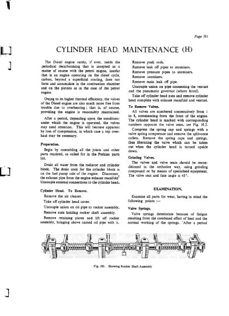
Fig. Hl Showing Rocker Shaft Assembly<br />
Page Hl<br />
Remove push rods.<br />
Remove leak off pipes to atomisers.<br />
Remove pressure pipes to atomisers.<br />
Remove atomisers.<br />
Remove main leak off pipe.<br />
Uncouple union on pipe connecting the venturi<br />
and the pneuma tic governor (where fitted).<br />
Take off cylinder head Duts and remove cylinder<br />
head complete with exhaust manifold and venturi.<br />
To Remove Valves.<br />
All valves are numbered consecutively from I<br />
to 8, commencing from the front of the engine.<br />
The cylinder head is marked with corresponding<br />
numbers opposite the valve seats, see Fig. H.2.<br />
Compress the spring cap and springs with a<br />
valve spring compressor and remove the split-cone<br />
collets. Remove the spring caps and springs,<br />
thus liberating the valve which can be taken<br />
out when the cylinder head is turned upside<br />
down.<br />
Grinding Valves.<br />
The valves and valve seats should be reconditioned<br />
in the orthodox way, using grinding<br />
compound or by means of specialised equipment.<br />
The valve seat and face angle is 45°,<br />
EXA1\IUN A nON.<br />
Examine all parts for wear, having in mind tbe<br />
following points:-<br />
Valve Springs.<br />
Valve springs deteriorate because of fatigue<br />
resulting from the combined effect of heat and the<br />
normal working of the springs. . Af ter aperiod


