Perkins L4 Workshop Manual - L-36 Fleet
Perkins L4 Workshop Manual - L-36 Fleet
Perkins L4 Workshop Manual - L-36 Fleet
You also want an ePaper? Increase the reach of your titles
YUMPU automatically turns print PDFs into web optimized ePapers that Google loves.
1 .<br />
..,<br />
~<br />
~<br />
,<br />
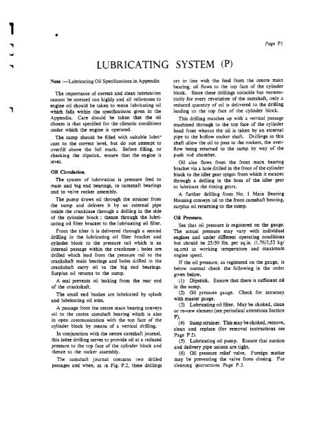
Note :-Lubricating Gil SpeciJications in Appendix<br />
Tbe importance of correct and clean lubrication<br />
cannot be stressed toa highly and all references to<br />
engine oil should be taken to mean lubricating oil<br />
which raIls within the specifications given in the<br />
Appendix. Care should be taken that the oil<br />
chosen is that specified for the climatic conditions<br />
undcr which the engine is operated.<br />
Tbe sump should be filled with suitable lubri-<br />
I."ant to the correct level, but do not attempt to<br />
overfill above the ruIl mark. Before filling, or<br />
checking the dipstick. ensure that the engine is<br />
level.<br />
Gil Circulation.<br />
Tbe system of lubrit:ation is pressure reed to<br />
main and big end beanngs, to camstlaft bearings<br />
and to vaJve rocker assembly.<br />
The pump draws oil through the strainer from<br />
the sump and delivers it by an extern al pipe<br />
inside tbe crankcase througb a drilling in tbe side<br />
of tbe cylinder block ; thence through the lubricating<br />
oil filter bracket to the lubricating oil filter.<br />
From the tilter it is delivered througb a second<br />
drilling in the lubricating oil filter bracket and<br />
cylinder block to the pressure rail wbich is an<br />
internal passage witbin the crankcase; holes are<br />
drilled which lead from the pressure rail to tbe<br />
crankshaft main hearings and holes dril led in tbe<br />
cranksbaft carry oil to the big end bearings.<br />
Surplus oil returns to the sump.<br />
A seal prevents oil leaking from the rear end<br />
of the crankshaft.<br />
The smalt end bushes are lubricated by splash<br />
and lubricating oil mist.<br />
A passage from tbe centre main bearing conveys<br />
oil to tbe centre camshaft hearing which is also<br />
in open communication with the top face of the<br />
cylinder block by means of a vertical drilling.<br />
In conjunction with tbe centre camshaft journal,<br />
this Jatter drilling serves to provide oil at a teduced<br />
pressure to tbe top face of tbe cylinder block and<br />
thence to the rocker assembly.<br />
The camshaft journal contains two drilled<br />
passages and when, as in Fig. P.2, these drillings<br />
SYSTEM<br />
CP)<br />
Page PI<br />
are in line with the feed from the centre main<br />
be.\ring, oil flows to the top face of the cylinder<br />
block. Since these drillings coincide but mom entarily<br />
for every revolution of the camshaft, only a<br />
reduced quantity of oil is delivered to the drilling<br />
leading to the top t:'lce of the cylinder block.<br />
This drilling matches up with a vertical passage<br />
machined through to the top face of the cylinder<br />
head from whence the oil is taken by an external<br />
pipe to the hollow rocker shaft. Drillings in th is<br />
shaft allow the oil to pass to the rockers, the overflow<br />
being returned to the sump by way of the<br />
push rod chamber.<br />
Gil also flows from the front main hearing<br />
bracket via a hole drilled in the front of the cylinder<br />
block to the idler gear spigot from which it escapes<br />
through a drilling in the boss of the idler gear<br />
to lubricate the timing gears.<br />
A further drilling from No. I Main Bearing<br />
Housing conveys oil to the front camshaft hearing,<br />
surplus oil returning to the sump.<br />
Oil Pressure.<br />
Sec tbat oil pressure is registered on the gauge.<br />
The actual pressure may vary with individua!<br />
engines and under different operating conditions<br />
but shou!d he 25/50 Ibs. per sq.in. (1.76/3.52 kg/<br />
sq.cm) at working temperature and maximum<br />
engine speed.<br />
Ir the oil pressure, as registered on the gauge, is<br />
below normal check the following in tbe order<br />
gJven below.<br />
(I) Dipstick. Ensure that there is sufficient oi!<br />
in the sump.<br />
(2) Oil pressure gauge. Check for accuracy<br />
with master gauge.<br />
(3) Lubricating oil filter. May be choked. clean<br />
or re-ncw element (see periodical attentions Section<br />
F). (4) Sump strainer. This may be choked, remove,<br />
clean and replace (for removal instructions sec<br />
Page P.2).<br />
(5) Lubricating oil pump. Ensure that suction<br />
and delivery pipe uni ons are tight.<br />
(6) Oil pressure relief valve. Foreign matter<br />
may be preventing the valve from closing. For<br />
cleaning ifistructions Page P .3.


