Perkins L4 Workshop Manual - L-36 Fleet
Perkins L4 Workshop Manual - L-36 Fleet
Perkins L4 Workshop Manual - L-36 Fleet
You also want an ePaper? Increase the reach of your titles
YUMPU automatically turns print PDFs into web optimized ePapers that Google loves.
. .<br />
~- Pag~<br />
..,<br />
Iel InjectÎon System-continued<br />
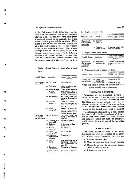
to the Cuet pump. Such difficulties, with the<br />
likely cause and suggested cure, are set out on the<br />
following ta bie. The fust move when a Cuel pump<br />
is suspected should be to uncouple the piping<br />
between the fuel pump and the atomisers. If the<br />
engine is then rotated with the pump con trol rod<br />
set at ruil load position it will be seen whether<br />
or not the Cuel is being deliver.ed. Observe each<br />
discharge outlet on the fuel pump to see if all<br />
discharge outlets are in order. On the following<br />
table the word .. pump " applies to the pump unit<br />
block as a whole or to individual elements, and<br />
the numbers reCerred 10 are shown in Fig. S.ll.<br />
1. Engine will not Start, or Stops af ter a short<br />
time.<br />
2. Engine does not pull.<br />
Quantity of (a) Delivery<br />
fuel delivered valve. 21<br />
per stroke<br />
insufficient.<br />
~b) Pressure<br />
system joints.<br />
3. Engine emits black smoke.<br />
57<br />
Ir leaking, clean joint<br />
races and tighten.<br />
Condition or sugaested<br />
Possible Cause. Location. remedy for correct<br />
working.<br />
Quantity of<br />
Cue! delivered<br />
per stroke<br />
excessive.<br />
Ca) Regulating<br />
quadrant, 24.<br />
Ir moved. duo to scrow<br />
being 10050, proceed as<br />
in (r)<br />
Condition or suggcsted<br />
Po~iblc Causc. Location. remedy for correct<br />
,<br />
Pump does not (a) Fuel cock.<br />
deliver fuel.<br />
(b) Fuel tank.<br />
(c) Fuel inlet pipe<br />
or filter<br />
elements.<br />
working.<br />
Must be open.<br />
Must contain an adequate<br />
supply.<br />
Clean pipes. examine<br />
filter elements and. if<br />
choked. clean them as<br />
Control rad (a) Pump Proceed as in (r)<br />
has jammcd. plunger. 20.<br />
(b) Control rod Proceed as in (r)<br />
NOTE : Ir air is in system, the suction side of lift<br />
pump should fust be examined.<br />
PNEUMAnc GOVERNOR<br />
...,<br />
,<br />
,<br />
Pump does<br />
not deliver<br />
fuel uniformly.<br />
(d) Air in pump.<br />
(e) Delivery<br />
Valve.21.<br />
(f) Pump<br />
plunger.20.<br />
(g) Air in pump.<br />
(h) Delivery valve<br />
spring, 22.<br />
(j) Delivery<br />
descnbed in Section G.<br />
Air vent filter and<br />
pump as described on<br />
page 56.<br />
Clean and inspect. Ir<br />
worn or damaged. replace<br />
both valve and<br />
seating.<br />
Return the pump in-<br />
tact to the nearest<br />
service station or to<br />
<strong>Perkins</strong> Engines ltd.<br />
Air vent filter and<br />
pump as described on<br />
page 56.<br />
Replace if broken.<br />
If damaged on face or<br />
Adjustment of tbe pneumatic govemor is<br />
etfected at the works when the engine is erected.<br />
It is an operation requiring considerable skill.<br />
Tbe idling stop on the buttertly valve and tbe<br />
adjusting screw on the cap of the govemor have<br />
to be manipulated altematively until smooth<br />
running at the desired idling speed is achieved.<br />
No subsequent adjustment is, in fact, needed.<br />
Any deterioration in the smoothness of idling is<br />
due to some defect which bas arisen elsewhele<br />
and should he looked for under the paragraphs<br />
in tbis section devoted to care of tbe fuel system<br />
generally.<br />
1<br />
valve.<br />
(k) Tappet<br />
spring, 1 S<br />
guide replace.<br />
See (f) above.<br />
MAINTENANCE<br />
...<br />
(1) Pump<br />
plunger. 20.<br />
(m) Fuel inlet<br />
pipes or filter<br />
elements.<br />
(n) Fuellift<br />
pump.<br />
5ee (f) above.<br />
Proceed as (c)<br />
This pump may not he<br />
operating efficiently.<br />
See instructions on<br />
page 56.<br />
Tbe tmiest pinhole or crack in the leather<br />
diaphragm will affect the operation of the governor.<br />
If such a .ault is suspected. test in this way.<br />
(a) Remove vacuüm pipe.<br />
(b) Move the stop lever into " stop" position.<br />
(c) Place a finger over the diaphragm housing<br />
:0) Tappet adjusting<br />
scrcw.<br />
:p) Cam profiles<br />
Proceed as in (f) above<br />
Proceed as in (f) above<br />
union in order to seal it.<br />
(d) Release the stop lever.<br />
I<br />
,<br />
J<br />
J


