

Perkins L4 Workshop Manual - L-36 Fleet
Perkins L4 Workshop Manual - L-36 Fleet
Perkins L4 Workshop Manual - L-36 Fleet

You also want an ePaper? Increase the reach of your titles
YUMPU automatically turns print PDFs into web optimized ePapers that Google loves.
1<br />
,<br />
Cylinder Head ..\-faintenance-eontinued<br />
Should it be necessary to remove these covers<br />
ncw copper joints should be fitted when they are<br />
replaced.<br />
lf ncw copper joints are not available the old<br />
unes may be used provided they are softened<br />
before being re-fitted.<br />
To soften the joints heat them to a dull red heat<br />
and quench in cold water.<br />
Special care is necessary when refitting these<br />
covers to ensure that there are no leaks at the<br />
joints otherwise there will be a loss of compression<br />
and the efficiency of the engine -:vill be impaired.<br />
Re-assembly Cylinder Head.<br />
Replace valves, valve springs, collars and collet~.<br />
Replace combustion chamber caps and joints.<br />
Fit exhaust manifold gaskets and exhaust<br />
manifold.<br />
Replacing Cylinder Head.<br />
Before replacing cylinder head it is extremely<br />
important to ensure that the cylinder block and<br />
cylinder head races are perfectly clean.<br />
When replacing the cylinder head a new gasket<br />
should be used. Cover both sides with a thin<br />
coating of good jointing compound and before<br />
placing over the cylinder head studs ensure that<br />
the gasket is correctly positioned. The gasket is<br />
marked to indicate hcw it should be replaced.<br />
Having placed the gas ket in position ensure that<br />
the cylinder bead face is perfectly clean and place<br />
in position over the cylinder head studs.<br />
[J.- @~6 2~ ."<br />
Page H3<br />
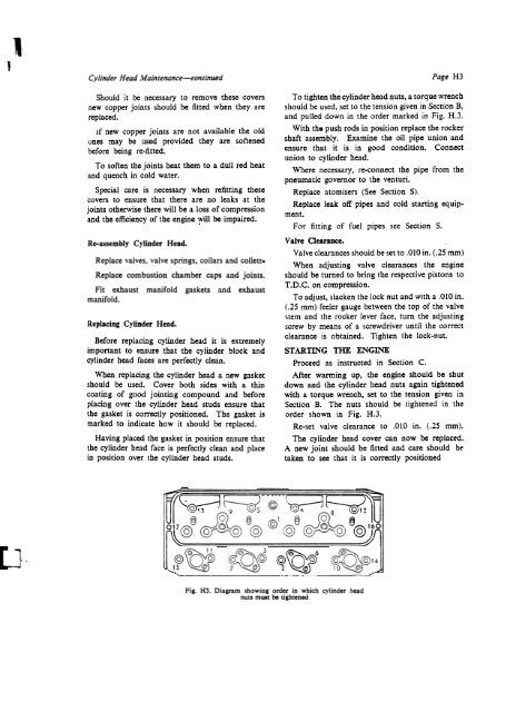
To tighten the cylinder head Duts, a torque wrench<br />
should be used, set to the tension given in Section B,<br />
and pulled down in the order marked in Fig. H.3.<br />
With tb. push rods in position replace tbe rocker<br />
shaft assembly. Examine the oil pipe union and<br />
ensure that it is in good condition. Connect<br />
union to cylinder head.<br />
Where necessary, re-connect the pipe from the<br />
pneumatic governor to the venturi.<br />
Replace atomisers (See Section S).<br />
Replace leak off pipes and cold starting equipment.<br />
For fitting of fuel pipes see Section S.<br />
Valve Clearance.<br />
Valve clearances should be set to .010 in. (.25 mIn)<br />
When adjusting valve clearances the engine<br />
should he turned to bring the respective pistons to<br />
T .D.C. on compression.<br />
To adjust, slacken the lock nut and with a .010 in.<br />
(.25 mm) feeIer gauge between the top of the valve<br />
stem and the rocker lever face, turn the adjusting<br />
screw by means of a screwdriver until the correct<br />
clearance is obtained. Tighten the lock-nut.<br />
STARTING THE ENGINE<br />
Proceed as instructed in Section C.<br />
Af ter warming up, tbe engine should be sbut<br />
down and the cylinder head Duts again tightened<br />
witb a torque wrench, set to the tension given in<br />
Section B. The nuts should be tightened in the<br />
order shown in Fig. H.3.<br />
Re-set valve clearance to .010 in. (.25 mm).<br />
Tbe cylinder head cover cao aow be replac~d.<br />
A ncw joint should be fitted and care should b~<br />
taken to sec that it is correctly positioned<br />
§<br />
'-;;;;'<br />
Fig. H3. Diagram showing order in which cylinder head<br />
nut.! must bc tightened


