Perkins L4 Workshop Manual - L-36 Fleet
Perkins L4 Workshop Manual - L-36 Fleet
Perkins L4 Workshop Manual - L-36 Fleet
You also want an ePaper? Increase the reach of your titles
YUMPU automatically turns print PDFs into web optimized ePapers that Google loves.
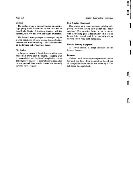
Page A2 Engine Description-continued<br />
Cooling.<br />
The cooling water is pump circulated by a centrifugal<br />
pump which is mounted on the front end of<br />
the cylinder block. ft is driven, together with the<br />
dynamo, bya Vee belt from the engine crankshaft.<br />
The internal water passages are arranged to give<br />
a brisk circulation of water around the combustion<br />
chamber and atomiser seating. The fan is mounted<br />
on the forward end of the water pump.<br />
Air Intake.<br />
A large air cleaner is fitted through which must<br />
pass alI air drawn into the engine. Harmful dust<br />
is th us excluded and the lire of the cylinders corres- .<br />
pondingly prolonged. The air cleaner is connected<br />
to the venturi inlet which houses the butterfly<br />
throttle valve con trol.<br />
Cold Starting Equipment.<br />
Comprises a hand pump, atomiser, priming tank,<br />
piping, induction heater and starter and heater<br />
switches. The induction heater is not in contact<br />
with the burning gases in the cylinder. It is located<br />
in the inlet venturi and is in use only during<br />
starting under very cold conditions.<br />
Electric Starting Equipment.<br />
A 12-volt starter is flange mounted on the<br />
flywheel housing.<br />
Dynamo.<br />
12-Volt ; earth return type complete with control<br />
box and fuse box. It is mounted on the off side<br />
of the cylinder block and is belt driven by a Vee.<br />
belt from the crankshaft.<br />
[<br />
r-


