

Perkins L4 Workshop Manual - L-36 Fleet
Perkins L4 Workshop Manual - L-36 Fleet
Perkins L4 Workshop Manual - L-36 Fleet

Create successful ePaper yourself
Turn your PDF publications into a flip-book with our unique Google optimized e-Paper software.
~<br />
Page Q2<br />
di stance piece and then press on front bearing.<br />
Ensure that each hearing end cover faces<br />
outwards towards the ends of the shaft.<br />
2. The front seal retaining plate should then he<br />
placed in position against the back face of<br />
the rear hearing. This retaining plate is<br />
. dished' and when positioned, the centre<br />
of the plate must not be in contact with the<br />
rear bearing.<br />
3. Fit the feit seal and seal housing, so that these<br />
bear on the retaining plate.<br />
4. Prcss the water pump thrower on to the shaft<br />
so that the thrower Range faces towards the<br />
rear bearing.<br />
S. The whole of the foregoing assembly should<br />
then be pressed into the water pump body<br />
from the front end, and the circlip securely<br />
positioned in the recess forward of the front<br />
bearing. Before pressing the assembly into<br />
the pump body, however, the bearings and<br />
the space between the two bearings should be<br />
half filled with a high melting point grease.<br />
6. Fit the rear seal into the pump body ensuring<br />
that the carbon face is positioned towards the<br />
rear ofthe pump body. When fitted, the seal<br />
must rest squarelyon its scat and not be<br />
canted in any way.<br />
7. At this stage the shaft should be turned by<br />
0<br />
~<br />
hand to ensure that ther\: is no undue re.<br />
.istance to rotation.<br />
8. Press on the pulley making certain that no<br />
rearward axial movemem of the shaft is<br />
incurred.<br />
9. The impelle( should now be pressed on to the<br />
shaft. With the impeller fitted. care should<br />
be taken to ensure that a clearance of .015-<br />
.025 in. (.38 to .64 mm) is maimained between<br />
the inner edge of the impeller vanes and the<br />
water pump body. As a guide to obtaining a<br />
correct clearance in this respect, the impeller<br />
should be so positioned as to allow a straight<br />
edge to simultaneously touch the back face of<br />
the pump body and the two raised extractor<br />
hole races in the teat of the impeller.<br />
10. Refit plain washer and slotted nut and secure<br />
with a new split pin.<br />
Modified Water Pump<br />
0 Cl)<br />
---<br />
@<br />
.015<br />
I<br />
~<br />
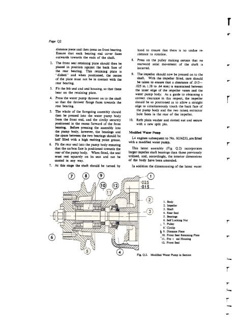
<strong>L4</strong> engines subsequent to No. 60<strong>36</strong>233, arc fittcd<br />
with a modificd water pump.<br />
This latcst assembly (Fig. Q.2) incorporates<br />
largcr impcller shaft bcarings than those prcviously<br />
utiliscd, and, accordingJy, thc interior dimensions<br />
of tbc body have been amcnded.<br />
-'<br />
~~~~~.7?"j<br />
In addition the dimensioning of the latcst water<br />
1. Body<br />
2. Impe11cr<br />
3. Shaft<br />
4. Rcar Scal<br />
5. Bcarings<br />
6. Sclf Locking Nut<br />
;. 7. Pulley<br />
8: Circlip<br />
k 9. Distancc Piccc<br />
'10. Front ScaI Rctaining Platc<br />
-11. Fro t cal Housing<br />
12. Front Scal<br />
0~. Q.l. Modified Water Pump in Section<br />
r<br />
f'"<br />
r<br />
,...<br />
r<br />
r<br />
r<br />
r<br />
r<br />
r<br />
-


