

Perkins L4 Workshop Manual - L-36 Fleet
Perkins L4 Workshop Manual - L-36 Fleet
Perkins L4 Workshop Manual - L-36 Fleet

You also want an ePaper? Increase the reach of your titles
YUMPU automatically turns print PDFs into web optimized ePapers that Google loves.
~ .<br />
..,<br />
-<br />
..,<br />
u<br />
~<br />
~<br />
1<br />
J<br />
]<br />
Fue/ lnjection System-continued<br />
The upper, and helical edge of the annular<br />
groove thus serves as a valve. The higher that<br />
edge is in relation to the top of the plunger the<br />
sooner the cut-oir and the less quantity of oil<br />
supplied to the atomiser per stroke.<br />
By varying the level of that edge the quantity<br />
of oil supplied is controlled.<br />
To alter that level, so that it uncovers the port<br />
in the pump barrel to vary the quantity of fuel<br />
delivered, the plunger is turned in its barre! by a<br />
simple means to he described shortly.<br />
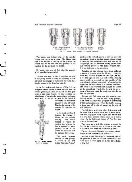
In the first and second sketches of Fig. S.2, the<br />
plunger is tumed to one extreme position with the<br />
vertical groove just clear of anc of the two port<br />
holes in the pump barrel. In that position the<br />
helical edge of the circular groove is at its lowest<br />
point and, so far as the port in tbc barrel is<br />
concemed the maximum<br />
quantity of oil is delivered.<br />
That is the setting of the<br />
plunger for starting tbc<br />
engine.<br />
In the third and fourth<br />
sketches the plunger is<br />
shown set fot normal<br />
running. The precise<br />
position is varied by<br />
tuming the plunger so<br />
that a greater or lesser<br />
quantity of oil is de-<br />
livered to conform with<br />
the demand for power.<br />
The otber extreme<br />
position of the plunger<br />
FIG. SJ. Pump element is shown in the fifth<br />
shown in section. sketch. This is the" stop .,<br />
Page S3<br />
position : the vertical groove is now in line with<br />
the delivery port to the fuel pump gallery, whicb<br />
is thus put into communication with the top of<br />
the plunger, and oil therefore, merely passes down<br />
this vertical groove as the pump plunger rises.<br />
It is not delivered to the atomisers.<br />
Rotation of the. plunger into these different<br />
positions is brought about in this war. Near the<br />
lower end of each plunger are two lugs (see Fig.<br />
5.3). The lugs are held in a slot on the actuating<br />
sleeve which is mounted on the outside of the<br />
pump barrel and can be rotated. Clamped to the<br />
upper end of each sleeve is a toothed quadrant.<br />
The teeth of the quadrant are engaged by a rack<br />
on the control rad (Fig. 5.11). To and fro movement<br />
of the rack turns the quadrants, the sleeves<br />
and the plungers.<br />
Between the fuel pump and the atomisers are<br />
delivery valves, 21, one to each pump plunger,<br />
these serve the important purpose of preventing<br />
dribble at the atomisers. They do that by causing<br />
a sharp cut off in the oil supply at the end of<br />
each injection.<br />
Fig. 5.4 shows a delivery valve. It is at one and<br />
the same time a poppet valve and a piston valve.<br />
The head is poppet valve shaped and below that<br />
is a cylindrical portion which serves as a piston<br />
valve. In the left-hand sketch of Fig. 5.4, the<br />
valve is shown closed.<br />
This valve bas a high lift, so that, as shown in<br />
Fig. 5.4 the cylindrical part of the valve rises clear<br />
of the valve scat when the valve is fully open.<br />
The war in which this valve operates to prevent<br />
dribble at the atomiser is as follows :-<br />
50 long as the fuel pump is delivering fuel oil<br />
the pressure of that oil on the underside of the<br />
valve keeps it wide open as in the third sketch<br />
of Fig. 5.4.


