

Avalon Interface Specifications (PDF) - Altera
Avalon Interface Specifications (PDF) - Altera
Avalon Interface Specifications (PDF) - Altera

Create successful ePaper yourself
Turn your PDF publications into a flip-book with our unique Google optimized e-Paper software.
2.1. Clock Sink<br />
2. <strong>Avalon</strong> Clock and Reset <strong>Interface</strong>s<br />
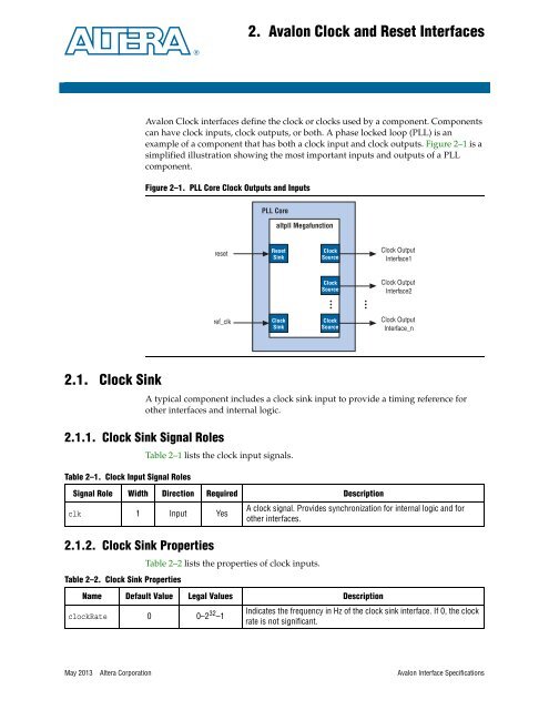
<strong>Avalon</strong> Clock interfaces define the clock or clocks used by a component. Components<br />
can have clock inputs, clock outputs, or both. A phase locked loop (PLL) is an<br />
example of a component that has both a clock input and clock outputs. Figure 2–1 is a<br />
simplified illustration showing the most important inputs and outputs of a PLL<br />
component.<br />
A typical component includes a clock sink input to provide a timing reference for<br />
other interfaces and internal logic.<br />
2.1.1. Clock Sink Signal Roles<br />
Table 2–1. Clock Input Signal Roles<br />
2.1.2. Clock Sink Properties<br />
Figure 2–1. PLL Core Clock Outputs and Inputs<br />
reset<br />
ref_clk<br />
PLL Core<br />
Table 2–1 lists the clock input signals.<br />
altpll Megafunction<br />
Reset<br />
Sink<br />
Clock<br />
Sink<br />
Table 2–2 lists the properties of clock inputs.<br />
Clock Output<br />
<strong>Interface</strong>1<br />
Clock Output<br />
<strong>Interface</strong>2<br />
Clock Output<br />
<strong>Interface</strong>_n<br />
May 2013 <strong>Altera</strong> Corporation <strong>Avalon</strong> <strong>Interface</strong> <strong>Specifications</strong><br />
Clock<br />
Source<br />
Clock<br />
Source<br />
Clock<br />
Source<br />
Signal Role Width Direction Required Description<br />
clk 1 Input Yes<br />
Table 2–2. Clock Sink Properties<br />
A clock signal. Provides synchronization for internal logic and for<br />
other interfaces.<br />
Name Default Value Legal Values Description<br />
clockRate 0 0–2 32 –1<br />
Indicates the frequency in Hz of the clock sink interface. If 0, the clock<br />
rate is not significant.


