

Avalon Interface Specifications (PDF) - Altera
Avalon Interface Specifications (PDF) - Altera
Avalon Interface Specifications (PDF) - Altera

Create successful ePaper yourself
Turn your PDF publications into a flip-book with our unique Google optimized e-Paper software.
5–4 Chapter 5: <strong>Avalon</strong> Streaming <strong>Interface</strong>s<br />
Signal Sequencing and Timing<br />
5.4. Signal Sequencing and Timing<br />
5.4.1. Synchronous <strong>Interface</strong><br />
5.4.2. Clock Enables<br />
This section provides information related to timing and sequencing of <strong>Avalon</strong>-ST<br />
interfaces.<br />
All transfers of an <strong>Avalon</strong>-ST connection occur synchronous to the rising edge of the<br />
associated clock signal. All outputs from a source interface to a sink interface,<br />
including the data, channel, and error signals, must be registered on the rising edge<br />
of clock. Inputs to a sink interface do not have to be registered. Registering signals at<br />
the source provides for high frequency operation while eliminating back-to-back<br />
registers with no intervening logic.<br />
<strong>Avalon</strong>-ST components typically do not include a clock enable input, because the<br />
<strong>Avalon</strong>-ST signaling itself is sufficient to determine the cycles that a component<br />
should and should not be enabled. <strong>Avalon</strong>-ST compliant components may have a<br />
clock enable input for their internal logic, but they must take care to ensure that the<br />
timing of the interface control signals still adheres to the protocol.<br />
5.5. <strong>Avalon</strong>-ST <strong>Interface</strong> Properties<br />
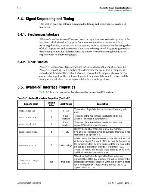
Table 5–2 lists the properties that characterize an <strong>Avalon</strong>-ST interface.<br />
Table 5–2. <strong>Avalon</strong>-ST <strong>Interface</strong> Properties (Part 1 of 2)<br />
Property Name<br />
Default<br />
Value<br />
symbolsPerBeat 1 1 – 32<br />
associatedClock 1<br />
associatedReset 1<br />
Legal Values Description<br />
Clock<br />
interface<br />
Reset<br />
interface<br />
dataBitsPerSymbol 8 1 – 512<br />
errorDescriptor 0 List of strings<br />
firstSymbolInHigh<br />
OrderBits<br />
true true, false<br />
The number of symbols that are transferred on every valid<br />
cycle.<br />
The name of the <strong>Avalon</strong> Clock interface to which this<br />
<strong>Avalon</strong>-ST interface is synchronous.<br />
The name of the <strong>Avalon</strong> Reset interface to which this<br />
<strong>Avalon</strong>-ST interface is synchronous.<br />
Defines the number of bits per symbol. For example,<br />
byte-oriented interfaces have 8-bit symbols. This value is not<br />
restricted to be a power of 2.<br />
A list of words that describe the error associated with each bit<br />
of the error signal. The length of the list must be the same as<br />
the number of bits in the error signal, and the first word in the<br />
list applies to the highest order bit. For example, “crc,<br />
overflow" means that bit[1] of error indicates a CRC error,<br />
and bit[0] indicates an overflow error.<br />
When true, the first-order symbol is driven to the most<br />
significant bits of the data interface. The highest-order symbol<br />
is labeled D0 in this specification. When this property is set to<br />
false, the first symbol appears on the low bits, that is, D0<br />
appears at data[7:0].<br />
<strong>Avalon</strong> <strong>Interface</strong> <strong>Specifications</strong> May 2013 <strong>Altera</strong> Corporation


