

Avalon Interface Specifications (PDF) - Altera
Avalon Interface Specifications (PDF) - Altera
Avalon Interface Specifications (PDF) - Altera

You also want an ePaper? Increase the reach of your titles
YUMPU automatically turns print PDFs into web optimized ePapers that Google loves.
5–6 Chapter 5: <strong>Avalon</strong> Streaming <strong>Interface</strong>s<br />
Data Layout<br />
5.8. Data Layout<br />
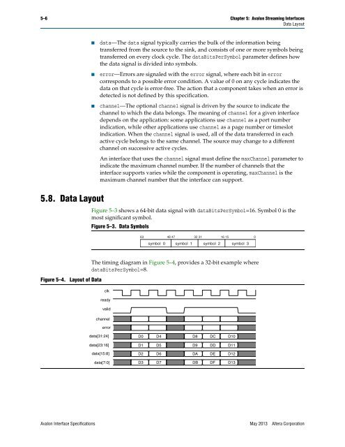
Figure 5–4. Layout of Data<br />
■ data—The data signal typically carries the bulk of the information being<br />
transferred from the source to the sink, and consists of one or more symbols being<br />
transferred on every clock cycle. The dataBitsPerSymbol parameter defines how<br />
the data signal is divided into symbols.<br />
■ error—Errors are signaled with the error signal, where each bit in error<br />
corresponds to a possible error condition. A value of 0 on any cycle indicates the<br />
data on that cycle is error-free. The action that a component takes when an error is<br />
detected is not defined by this specification.<br />
■ channel—The optional channel signal is driven by the source to indicate the<br />
channel to which the data belongs. The meaning of channel for a given interface<br />
depends on the application: some applications use channel as a port number<br />
indication, while other applications use channel as a page number or timeslot<br />
indication. When the channel signal is used, all of the data transferred in each<br />
active cycle belongs to the same channel. The source may change to a different<br />
channel on successive active cycles.<br />
An interface that uses the channel signal must define the maxChannel parameter to<br />
indicate the maximum channel number. If the number of channels that the<br />
interface supports varies while the component is operating, maxChannel is the<br />
maximum channel number that the interface can support.<br />
Figure 5–3 shows a 64-bit data signal with dataBitsPerSymbol=16. Symbol 0 is the<br />
most significant symbol.<br />
Figure 5–3. Data Symbols<br />
63 48 47 32 31 16 15 0<br />
symbol 0 symbol 1 symbol 2 symbol 3<br />
The timing diagram in Figure 5–4, provides a 32-bit example where<br />
dataBitsPerSymbol=8.<br />
clk<br />
ready<br />
valid<br />
channel<br />
error<br />
data[31:24]<br />
data[23:16]<br />
data[15:8]<br />
data[7:0]<br />
D0 D4 D8<br />
D1<br />
D2<br />
D3<br />
D5<br />
D6<br />
D7<br />
<strong>Avalon</strong> <strong>Interface</strong> <strong>Specifications</strong> May 2013 <strong>Altera</strong> Corporation<br />
D9<br />
DA<br />
DB<br />
DC<br />
DD<br />
DE<br />
DF<br />
D10<br />
D11<br />
D12<br />
D13


