- Page 1 and 2:
CCNA Complete Guide 2nd Edition Yap
- Page 3 and 4:
CCNA Complete Guide 2nd Edition Cop
- Page 5 and 6:
Upper Layers Lower Layers Applicati
- Page 7 and 8:
Cisco Hierarchical Model - Defined
- Page 9 and 10:
This page is intentionally left bla
- Page 11 and 12:
Header Length (4) Source Port (16)
- Page 13 and 14:
- Socket is a communication channel
- Page 15 and 16:
- The length of an IP address is 32
- Page 17 and 18:
- The following section discusses s
- Page 19 and 20:
This page is intentionally left bla
- Page 21 and 22:
- Below lists the 2 sublayers in th
- Page 23 and 24:
- Each switch port does not share t
- Page 25 and 26:
- Below lists the switch internal p
- Page 27 and 28:
Physical Layer - The physical layer
- Page 29 and 30:
- Another way to reduce emissions i
- Page 31 and 32:
Figure 3-7: Single-Mode and Multimo
- Page 33 and 34:
Wireless AP Switch Figure 3-8: 802.
- Page 35 and 36:
- Below lists the common IOS CLI er
- Page 37 and 38:
RT1#show running-config interface F
- Page 39 and 40:
- Cisco IOS treats a mistyped comma
- Page 41 and 42:
This page is intentionally left bla
- Page 43 and 44:
- Below describes the STP convergen
- Page 45 and 46:
- Refer back to Figure 5-1B, assume
- Page 47 and 48:
- A switch running RSTP only need 6
- Page 49 and 50:
Port Security Configuration - Port
- Page 51 and 52:
SW2# 00:25:00: STP: VLAN0001 new ro
- Page 53 and 54:
This page is intentionally left bla
- Page 55 and 56:
- Both protocols utilize a 12-bit V
- Page 57 and 58:
Layer 4 Switching (Content Switchin
- Page 59 and 60:
- VTP Pruning provides a way to pre
- Page 61 and 62:
VLAN Trunking Protocol Configuratio
- Page 63 and 64:
- VLAN information will not be prop
- Page 65 and 66:
- Private IP addresses are non-rout
- Page 67 and 68:
- Some materials calculate the numb
- Page 69 and 70:
This page is intentionally left bla
- Page 71 and 72:
Cisco Discovery Protocol (CDP) c250
- Page 73 and 74:
- CDP is enabled by default. The no
- Page 75 and 76:
Troubleshooting IP - Internet Contr
- Page 77 and 78:
- Firstly, PC1 purposely sends out
- Page 79 and 80:
- Below describes the operation of
- Page 81 and 82:
Maximum Hop Count Hop count metric
- Page 83 and 84:
- Invalid Timer specifies how long
- Page 85 and 86:
- Initial configuration on RT2: Rou
- Page 87 and 88:
- Static Routing configuration on R
- Page 89 and 90:
- RIPv1 and IGRP are classful routi
- Page 91 and 92:
- IGRP configuration on RT2: RT2(co
- Page 93 and 94:
MISC IP Routing Commands - The pass
- Page 95 and 96:
- OSPF uses a reliable protocol to
- Page 97 and 98:
- OSPF areas break up a network so
- Page 99 and 100:
- EIGRP uses the same formula as us
- Page 101 and 102:
- Autosummarization EIGRP supports
- Page 103 and 104:
- OSPF Single-Area configuration on
- Page 105 and 106:
- The show ip ospf database EXEC co
- Page 107 and 108:
OSPF Multiarea Configuration Area 1
- Page 109 and 110: - Below lists the different termino
- Page 111 and 112: - Verify the EIGRP configuration on
- Page 113 and 114: - When a link to a neighbor fails,
- Page 115 and 116: - Below shows the beauty of VLSM. B
- Page 117 and 118: - RT1 and RT3 are summarizing route
- Page 119 and 120: This page is intentionally left bla
- Page 121 and 122: - RIPv1 and IGRP perform autosummar
- Page 123 and 124: RT1#sh ip route Gateway of last res
- Page 125 and 126: MTU and Fragmentation - Maximum Tra
- Page 127 and 128: - Figure 17-1 shows the usage of CI
- Page 129 and 130: - Static NAT performs one-to-one ma
- Page 131 and 132: 172.16.1.1 172.16.1.2 172.16.1.3 17
- Page 133 and 134: This page is intentionally left bla
- Page 135 and 136: - Below shows the IP NAT debugging
- Page 137 and 138: - The access list indicates whether
- Page 139 and 140: - Access Control List (ACL) is the
- Page 141 and 142: - Below lists some other usages of
- Page 143 and 144: - Standard IP Access Lists configur
- Page 145 and 146: RT2#sh access-lists example01 Exten
- Page 147 and 148: WAN Network RT1 CSU/DSU CSU/DSU RT2
- Page 149 and 150: Remote Access Technologies - Remote
- Page 151 and 152: Digital Subscriber Lines (DSL) - DS
- Page 153 and 154: Point-to-Point Serial Links (Leased
- Page 155 and 156: - Comparisons between synchronous a
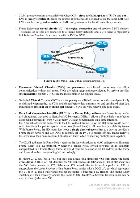
- Page 157 and 158: - PPP Encapsulation configuration o
- Page 159: - The function of the username {rem
- Page 163 and 164: - Comparisons between Frame Relay L
- Page 165 and 166: RT1 RT2 RT3 Figure 23-7A: RT1 with
- Page 167 and 168: This page is intentionally left bla
- Page 169 and 170: - IETF Frame Relay encapsulation ty
- Page 171 and 172: RT1 Frame Relay RT2 DLCI 101 Frame
- Page 173 and 174: - The interface serialx.y point-to-
- Page 175 and 176: - Frame Relay Multipoint Subinterfa
- Page 177 and 178: - Rate Shifting or Adaptive Rate Se
- Page 179 and 180: - By operating in the 5GHz radio ba
- Page 181 and 182: - Every packet from every access po
- Page 183 and 184: Virtual Interface (mandatory) Servi
- Page 185 and 186: Wireless Security - Organizations t
- Page 187 and 188: Wireless Management - WLANs require
- Page 189 and 190: Cisco Wireless LAN Configuration -
- Page 191 and 192: - ISDN offers very fast call setup
- Page 193 and 194: - ISDN was designed to reuse the ex
- Page 195 and 196: - ISDN PRIs are often being used fo
- Page 197 and 198: - Routing protocols are unable to l
- Page 199 and 200: DDR Step 4: Determining when to ter
- Page 201 and 202: - The show interfaces bri{num:0 | 1
- Page 203 and 204: DDR Dialer Profiles Configuration -
- Page 205 and 206: - Note: IP addresses are configured
- Page 207 and 208: - Below show the routing tables on
- Page 209 and 210: - The configuration above defines 2
- Page 211 and 212:
cisco Systems, Inc. 170 West Tasman
- Page 213 and 214:
Catalyst Switch IOS Upgrade Procedu
- Page 215 and 216:
Catalyst Switch IOS Upgrade Procedu
- Page 217 and 218:
Cisco Router Password Recovery Proc
- Page 219 and 220:
Catalyst Switch Password Recovery P
- Page 221 and 222:
Switch> Switch>en Switch#rename con
- Page 223 and 224:
- The 3 possible Frame Relay PVC st
- Page 225 and 226:
Constructing a Compound Frame Relay
- Page 227 and 228:
This page is intentionally left bla
- Page 229 and 230:
8. Once the frame is completed, it
- Page 231 and 232:
This page is intentionally left bla
- Page 233 and 234:
This page is intentionally left bla
- Page 235 and 236:
Decimal Hex Binary Decimal Hex Bina
- Page 237 and 238:
This page is intentionally left bla
- Page 239 and 240:
MISC Basic Networking Notes - The m
- Page 241 and 242:
MISC Data Link Layer Notes - Ethern
- Page 243 and 244:
- The 5-4-3 repeater deployment rul
- Page 245 and 246:
Ethernet Autonegotiation and Duplex
- Page 247 and 248:
The TCP Connection States timeout s
- Page 249 and 250:
- Q: How does a client application
- Page 251 and 252:
- Urgent Data Pointer (16 bits) ind
- Page 253 and 254:
TCP Selective Acknowledgment (SACK)
- Page 255 and 256:
- Local Proxy ARP is used when ther
- Page 257 and 258:
Spanning Tree Protocol Port ID - Wh
- Page 259 and 260:
The Problem of Router-on-a-Stick Co
- Page 261 and 262:
- Sample Subnet Zero configuration:
- Page 263 and 264:
The permanent keyword in the Static
- Page 265 and 266:
RIPv1 and VLSM RT1 RT4 Figure A6-9:
- Page 267 and 268:
- Below shows the NAT operations on
- Page 269 and 270:
Bidirectional (2-Way) NAT PC1 172.1
- Page 271 and 272:
- Note: A router does not require a
- Page 273 and 274:
The Access Control List established
- Page 275 and 276:
Switch Port Access Control Lists -
- Page 277 and 278:
- Below shows a sample Dynamic Acce
- Page 279 and 280:
Router(config)#ip access-list exten
- Page 281 and 282:
Optional PPP Commands - The compres
- Page 283 and 284:
- Below shows the output of the PPP
- Page 285 and 286:
- Below shows the output of the PPP
- Page 287 and 288:
- Below configure the username and
- Page 289 and 290:
IEEE 802.11 Standards and Specifica
- Page 291 and 292:
- Figure A6-20 shows the frame form
- Page 293 and 294:
- Below lists the IEEE 802.11 manag
- Page 295 and 296:
IEEE 802.11 Types and Subtypes Type
- Page 297 and 298:
Client (Supplicant) EAPOL-Start EAP
- Page 299 and 300:
- IPsec-based VPN is comprised of 2
- Page 301 and 302:
- IPsec supports the following 3 ty
- Page 303 and 304:
Version Header Length Time To Live
- Page 305 and 306:
- The authentication pre-share ISAK
- Page 307 and 308:
Troubleshooting ISDN E1/T1 Physical
- Page 309 and 310:
- Below addresses ISDN E1/T1 contro
- Page 311 and 312:
Troubleshooting ISDN Layer 2 - Unde
- Page 313 and 314:
Troubleshooting ISDN Layer 3 - Only
- Page 315 and 316:
ISDN Loopback Test Call - In a loop
- Page 317 and 318:
96 Number changed. The called numbe
- Page 319 and 320:
C2 Channel type not implemented. Th
- Page 321 and 322:
This page is intentionally left bla
- Page 323 and 324:
locking state, STP, 39 BNC, 27 bool
- Page 325 and 326:
show vlan, 57 show vtp status, 58 s
- Page 327 and 328:
framing, 22 MAC addresses, 22 stand
- Page 329 and 330:
K keepalives EIGRP, 95 Frame Relay,
- Page 331 and 332:
PAT (Port Address Translation), 127
- Page 333 and 334:
star topologies, 25 startup-config