

CCNA Complete Guide 2nd Edition.pdf - Cisco Learning Home
CCNA Complete Guide 2nd Edition.pdf - Cisco Learning Home
CCNA Complete Guide 2nd Edition.pdf - Cisco Learning Home

You also want an ePaper? Increase the reach of your titles
YUMPU automatically turns print PDFs into web optimized ePapers that Google loves.
Appendix 3<br />
The IP Routing Process<br />
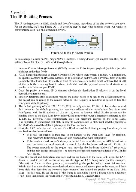
The IP routing process is fairly simple and doesn’t change, regardless of the size network you have.<br />
For an example, we’ll use Figure A3-1 to describe step by step what happens when PC1 wants to<br />
communicate with PC2 on a different network.<br />
PC1 PC2<br />
RT1<br />
E0<br />
E1<br />
172.16.1.1<br />
172.16.2.1<br />
172.16.1.2 172.16.2.2<br />
Figure A3-1: The IP Routing Process<br />
In this example, a user on PC1 pings PC2’s IP address. Routing doesn’t get simpler than this, but it<br />
still involves a lot of steps. Let’s work through them:<br />
1. Internet Control Message Protocol (ICMP) creates an Echo Request payload (which is just the<br />
alphabet in the data field).<br />
2. ICMP hands that payload to Internet Protocol (IP), which then creates a packet. At a minimum,<br />
this packet contains an IP source address, an IP destination address, and a Protocol field with 01h<br />
(remember that <strong>Cisco</strong> likes to use 0x in front of hex characters, so this could look like 0x01). All<br />
of that tells the receiving host to whom it should hand the payload when the destination is<br />
reached – in this example, ICMP.<br />
3. Once the packet is created, IP determines whether the destination IP address is on the local<br />
network or a remote one.<br />
4. Since IP determines this is a remote request, the packet needs to be sent to the default gateway so<br />
the packet can be routed to the remote network. The Registry in Windows is parsed to find the<br />
configured default gateway.<br />
5. The default gateway of host 172.16.1.2 (PC1) is configured to 172.16.1.1. To be able to send<br />
this packet to the default gateway, the hardware address of the router’s interface Ethernet0<br />
(configured with the IP address of 172.16.1.1) must be known. Why? So the packet can be<br />
handled down to the Data Link layer, framed, and sent to the router’s interface connected to the<br />
172.16.1.0 network. Hosts communicate only via hardware address on the local LAN.<br />
It is important to understand that PC1, in order to communicate to PC2, must send the packets to<br />
the MAC address of the default gateway on the local network.<br />
6. Next, the ARP cache is checked to see if the IP address of the default gateway has already been<br />
resolved to a hardware address:<br />
If it has, the packet is then free to be handed to the Data Link layer for framing.<br />
(The hardware destination address is also handed down with that packet.)<br />
If the hardware address isn’t already in the ARP cache of the host, an ARP broadcast is<br />
sent out onto the local network to search for the hardware address of 172.16.1.1.<br />
The router responds to the request and provides the hardware address of Ethernet0,<br />
and the host caches this address. The router also caches the hardware address of PC1 in its<br />
ARP cache.<br />
7. Once the packet and destination hardware address are handed to the Data Link layer, the LAN<br />
driver is used to provide media access via the type of LAN being used (in this example,<br />
Ethernet). A frame is then generated, encapsulating the packet with control information.<br />
Within that frame are the hardware destination and source addresses, plus in this case, an Ether-<br />
Type field that describes the Network layer protocol that handed the packet to the Data Link<br />
layer – in this case, IP. At the end of the frame is something called a Frame Check Sequence<br />
(FCS) field that houses the result of the Cyclic Redundancy Check (CRC).<br />
225<br />
Copyright © 2008 Yap Chin Hoong<br />
yapchinhoong@hotmail.com


