

CCNA Complete Guide 2nd Edition.pdf - Cisco Learning Home
CCNA Complete Guide 2nd Edition.pdf - Cisco Learning Home
CCNA Complete Guide 2nd Edition.pdf - Cisco Learning Home

You also want an ePaper? Increase the reach of your titles
YUMPU automatically turns print PDFs into web optimized ePapers that Google loves.
- The interface serialx.y point-to-point global configuration command creates a logical<br />
subinterface numbered y under physical interface serialx, and the frame-relay interface-dlci<br />
{dlci} subinterface subcommand statically associates and maps a local DLCI with an IP address<br />
on a subinterface. This ensures a router associate the correct PVC with the corresponding<br />
subinterface when it receives LMI messages regarding a PVC (up / down).<br />
- The subinterface and DLCI number do not have to be matched on both end routers of a PVC.<br />
However, it is a best practice to assign a subinterface number that matches the DLCI value<br />
assigned to the subinterface for easier administration and troubleshooting.<br />
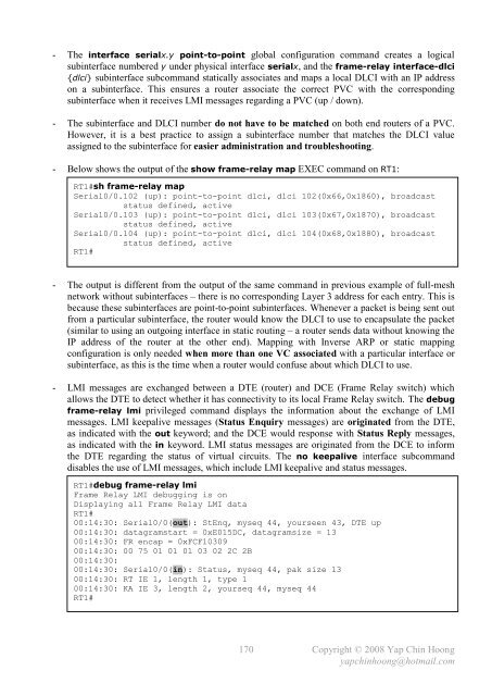
- Below shows the output of the show frame-relay map EXEC command on RT1:<br />
RT1#sh frame-relay map<br />
Serial0/0.102 (up): point-to-point dlci, dlci 102(0x66,0x1860), broadcast<br />
status defined, active<br />
Serial0/0.103 (up): point-to-point dlci, dlci 103(0x67,0x1870), broadcast<br />
status defined, active<br />
Serial0/0.104 (up): point-to-point dlci, dlci 104(0x68,0x1880), broadcast<br />
status defined, active<br />
RT1#<br />
- The output is different from the output of the same command in previous example of full-mesh<br />
network without subinterfaces – there is no corresponding Layer 3 address for each entry. This is<br />
because these subinterfaces are point-to-point subinterfaces. Whenever a packet is being sent out<br />
from a particular subinterface, the router would know the DLCI to use to encapsulate the packet<br />
(similar to using an outgoing interface in static routing – a router sends data without knowing the<br />
IP address of the router at the other end). Mapping with Inverse ARP or static mapping<br />
configuration is only needed when more than one VC associated with a particular interface or<br />
subinterface, as this is the time when a router would confuse about which DLCI to use.<br />
- LMI messages are exchanged between a DTE (router) and DCE (Frame Relay switch) which<br />
allows the DTE to detect whether it has connectivity to its local Frame Relay switch. The debug<br />
frame-relay lmi privileged command displays the information about the exchange of LMI<br />
messages. LMI keepalive messages (Status Enquiry messages) are originated from the DTE,<br />
as indicated with the out keyword; and the DCE would response with Status Reply messages,<br />
as indicated with the in keyword. LMI status messages are originated from the DCE to inform<br />
the DTE regarding the status of virtual circuits. The no keepalive interface subcommand<br />
disables the use of LMI messages, which include LMI keepalive and status messages.<br />
RT1#debug frame-relay lmi<br />
Frame Relay LMI debugging is on<br />
Displaying all Frame Relay LMI data<br />
RT1#<br />
00:14:30: Serial0/0(out): StEnq, myseq 44, yourseen 43, DTE up<br />
00:14:30: datagramstart = 0xE015DC, datagramsize = 13<br />
00:14:30: FR encap = 0xFCF10309<br />
00:14:30: 00 75 01 01 01 03 02 2C 2B<br />
00:14:30:<br />
00:14:30: Serial0/0(in): Status, myseq 44, pak size 13<br />
00:14:30: RT IE 1, length 1, type 1<br />
00:14:30: KA IE 3, length 2, yourseq 44, myseq 44<br />
RT1#<br />
_<br />
170<br />
Copyright © 2008 Yap Chin Hoong<br />
yapchinhoong@hotmail.com


