

Intelligent Transport Systems - Telenor
Intelligent Transport Systems - Telenor
Intelligent Transport Systems - Telenor

Create successful ePaper yourself
Turn your PDF publications into a flip-book with our unique Google optimized e-Paper software.
• NF-6 Availability: The user should be able to<br />
connect to the network and register with the<br />
service in 90 % of the cases.<br />
• NF-7 Reliability: The service should run without<br />
problems for 12 hours without the user<br />
needing to restart the application. If disconnected,<br />
the user should be able to continue the<br />
session when logging on within 5 minutes.<br />
• NF-8 Cost: The user should be able to control<br />
the cost of the service usage, for instance by<br />
choosing how often to poll for incoming messages.<br />
• NF-9 Response time: The user should receive<br />
response from the relay within the poll interval<br />
(which can be set by the user).<br />
4 Service Design<br />
This section will go through the design phase,<br />
and the class-, state-, sequence-, and collaboration<br />
diagrams of UML will illustrate this. A<br />
class diagram shows how the classes of a system<br />
relate to one another, while the state diagram<br />
focuses on the state changes in just one object.<br />
State diagram for the client will be presented<br />
here. While the sequence diagram shows how<br />
objects communicate with each other over time,<br />
collaboration diagrams show how objects interact<br />
according to space.<br />
4.1 The Architecture<br />
The architecture is dependent on the network<br />
technology used. This prototype will use the<br />
JXTA network technology [4], and the JXTA<br />
for J2ME package that is designed for J2ME<br />
enabled devices.<br />
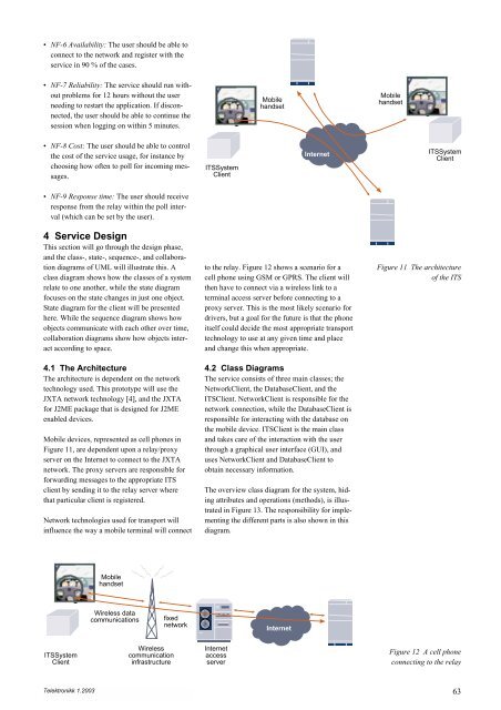
Mobile devices, represented as cell phones in<br />
Figure 11, are dependent upon a relay/proxy<br />
server on the Internet to connect to the JXTA<br />
network. The proxy servers are responsible for<br />
forwarding messages to the appropriate ITS<br />
client by sending it to the relay server where<br />
that particular client is registered.<br />
Network technologies used for transport will<br />
influence the way a mobile terminal will connect<br />
ITSSystem<br />
Client<br />
Telektronikk 1.2003<br />
Mobile<br />
handset<br />
Wireless data<br />
communications<br />
Wireless<br />
communication<br />
infrastructure<br />
fixed<br />
network<br />
ITSSystem<br />
Client<br />
Mobile<br />
handset<br />
Internet<br />
to the relay. Figure 12 shows a scenario for a<br />
cell phone using GSM or GPRS. The client will<br />
then have to connect via a wireless link to a<br />
terminal access server before connecting to a<br />
proxy server. This is the most likely scenario for<br />
drivers, but a goal for the future is that the phone<br />
itself could decide the most appropriate transport<br />
technology to use at any given time and place<br />
and change this when appropriate.<br />
4.2 Class Diagrams<br />
The service consists of three main classes; the<br />
NetworkClient, the DatabaseClient, and the<br />
ITSClient. NetworkClient is responsible for the<br />
network connection, while the DatabaseClient is<br />
responsible for interacting with the database on<br />
the mobile device. ITSClient is the main class<br />
and takes care of the interaction with the user<br />
through a graphical user interface (GUI), and<br />
uses NetworkClient and DatabaseClient to<br />
obtain necessary information.<br />
The overview class diagram for the system, hiding<br />
attributes and operations (methods), is illustrated<br />
in Figure 13. The responsibility for implementing<br />
the different parts is also shown in this<br />
diagram.<br />
Internet<br />
access<br />
server<br />
Internet<br />
Mobile<br />
handset<br />
ITSSystem<br />
Client<br />
Figure 11 The architecture<br />
of the ITS<br />
Figure 12 A cell phone<br />
connecting to the relay<br />
63


