Polymers in Confined Geometry.pdf
Polymers in Confined Geometry.pdf
Polymers in Confined Geometry.pdf

Create successful ePaper yourself
Turn your PDF publications into a flip-book with our unique Google optimized e-Paper software.
22 CHAPTER 3. POLYMERS IN CONFINED GEOMETRY<br />
d<br />
ld<br />
r<br />
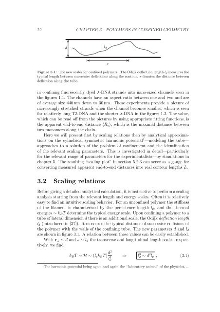
Figure 3.1: The new scales for conf<strong>in</strong>ed polymers. The Odijk deflection length ld measures the<br />
typical length between successive deflections along the contour. r denotes the distance between<br />
deflection along the tube.<br />
<strong>in</strong> conf<strong>in</strong><strong>in</strong>g fluorescently dyed λ-DNA strands <strong>in</strong>to nano-sized channels seen <strong>in</strong><br />
the figures 1.1. The channels have an aspect ratio between one and two and are<br />
of average size 440 nm down to 30 nm. These experiments provide a picture of<br />
<strong>in</strong>creas<strong>in</strong>gly stretched strands when the channel becomes smaller, which is seen<br />
for relatively long T2-DNA and the shorter λ-DNA <strong>in</strong> the figures 1.2. The value,<br />
which can be read off from the pictures by us<strong>in</strong>g appropriate fitt<strong>in</strong>g functions, is<br />
the apparent end-to-end distance 〈Ra〉, which is the maximal distance between<br />
two monomers along the cha<strong>in</strong>.<br />
Here we will present first by scal<strong>in</strong>g relations then by analytical approximations<br />
on the cyl<strong>in</strong>drical symmetric harmonic potential 1 —model<strong>in</strong>g the tube—<br />
approaches to a solution of the problem of conf<strong>in</strong>ement and the identification<br />
of the relevant scal<strong>in</strong>g parameters. This is <strong>in</strong>vestigated <strong>in</strong> detail—particularly<br />
for the relevant range of parameters for the experimentalists—by simulations <strong>in</strong><br />
chapter 5. The result<strong>in</strong>g “scal<strong>in</strong>g plot” <strong>in</strong> section 5.2.3 can serve as a gauge for<br />
convert<strong>in</strong>g measured apparent end-to-end distances <strong>in</strong>to real contour lengths L.<br />
3.2 Scal<strong>in</strong>g relations<br />
Before giv<strong>in</strong>g a detailed analytical calculation, it is <strong>in</strong>structive to perform a scal<strong>in</strong>g<br />
analysis start<strong>in</strong>g from the relevant length and energy scales. Often it is relatively<br />
easy to f<strong>in</strong>d an <strong>in</strong>tuitive scal<strong>in</strong>g behavior. For an unconf<strong>in</strong>ed polymer the stiffness<br />
of the filament is characterized by the persistence length lp, and the thermal<br />
energies ∼ kBT determ<strong>in</strong>e the typical energy scale. Upon conf<strong>in</strong><strong>in</strong>g a polymer to a<br />
tube of lateral dimension d there is an additional scale, the Odijk deflection length<br />
ld (<strong>in</strong>troduced <strong>in</strong> [37]). It measures the typical distance of successive collisions of<br />
the polymer with the walls of the conf<strong>in</strong><strong>in</strong>g tube. The new parameters d and ld<br />
are shown <strong>in</strong> figure 3.1. A relation between these values can be easily established.<br />
With r⊥ ∼ d and s ∼ ld the transverse and longitud<strong>in</strong>al length scales, respectively,<br />
we f<strong>in</strong>d<br />
kBT ∼ H ∼ (lpkBT ) d2<br />
l 3 d<br />
⇒ l 3 d ∼ d 2 lp , (3.1)<br />
1 The harmonic potential be<strong>in</strong>g aga<strong>in</strong> and aga<strong>in</strong> the “laboratory animal” of the physicist. . .