pdf, 12 MiB - Infoscience - EPFL
pdf, 12 MiB - Infoscience - EPFL
pdf, 12 MiB - Infoscience - EPFL

You also want an ePaper? Increase the reach of your titles
YUMPU automatically turns print PDFs into web optimized ePapers that Google loves.
Analysis of the final scour<br />
20%<br />
1° 2° 4° without ribs<br />
Scour reduction [%]<br />
0%<br />
-20%<br />
-40%<br />
S=0.5%, Q=150 l/s<br />
S=0.7%, Q=150 l/s<br />
S=0.5%, Q=180 l/s<br />
S=0.7%, Q=180 l/s<br />
S=0.5%, Q=210 l/s<br />
S=0.7%, Q=210 l/s<br />
0 15 30 45 60 75<br />
Rib-spacing / rib-depth: e s /e d [mm]<br />
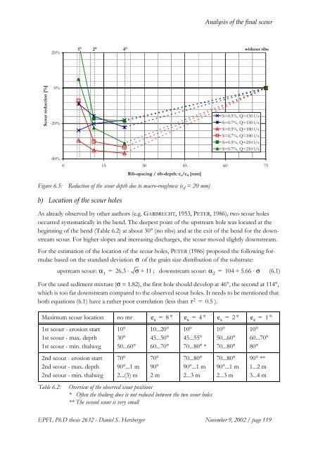
Figure 6.5: Reduction of the scour depth due to macro-roughness (e d = 20 mm)<br />
b) Location of the scour holes<br />
As already observed by other authors (e.g. GARBRECHT, 1953, PETER, 1986), two scour holes<br />
occurred systematically in the bend. The deepest point of the upstream hole was located at the<br />
beginning of the bend (Table 6.2) at about 30° (no ribs) and at the exit of the bend for the downstream<br />
scour. For higher slopes and increasing discharges, the scour moved slightly downstream.<br />
For the estimation of the location of the scour holes, PETER (1986) proposed the following formulae<br />
based on the standard deviation σ of the grain size distribution of the substrate:<br />
upstream scour: α 1<br />
= 26.3 ⋅ σ + 11 ; downstream scour: α 2<br />
= 104 + 5.66 ⋅ σ (6.1)<br />
For the used sediment mixture (σ = 1.82), the first hole should develop at 46°, the second at 114°,<br />
which is too far downstream compared to the observed scour holes. It needs to be mentioned that<br />
both equations (6.1) have a rather poor correlation (less than r 2 = 0.5 ).<br />
Maximum scour location no mr e s = 8 ° e s = 4 ° e s = 2 ° e s = 1 °<br />
1st scour - erosion start<br />
1st scour - max. depth<br />
1st scour - min. thalweg<br />
2nd scour - erosion start<br />
2nd scour - max. depth<br />
2nd scour - min. thalweg<br />
Table 6.2:<br />
10°<br />
30°<br />
50...60°<br />
70°<br />
90°...1 m<br />
2...(3) m<br />
10...20°<br />
45...50°<br />
60...70°<br />
70°<br />
90°<br />
2m<br />
10°<br />
45...55°<br />
70...80° *<br />
70...80°<br />
90°...1 m<br />
2...3 m<br />
Overview of the observed scour positions<br />
* Often the thalweg does is not reduced between the two scour holes<br />
** The second scour is very small<br />
10°<br />
50...60°<br />
70...80°<br />
70...80°<br />
90°...1 m<br />
2...3 m<br />
10°<br />
60...70°<br />
80°<br />
90° **<br />
1...2 m<br />
3...4 m<br />
<strong>EPFL</strong> Ph.D thesis 2632 - Daniel S. Hersberger November 9, 2002 / page 119