pdf, 12 MiB - Infoscience - EPFL
pdf, 12 MiB - Infoscience - EPFL
pdf, 12 MiB - Infoscience - EPFL

Create successful ePaper yourself
Turn your PDF publications into a flip-book with our unique Google optimized e-Paper software.
Chapter 6 - Analysis of the test results<br />
b) Velocities in the cross-section - secondary current<br />
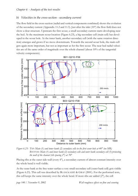
The flow field in the cross-section (radial and vertical components combined) shows the evolution<br />
of the secondary current (Appendix 11.2 and 11.5). Just after the inlet (10°) the flow field does not<br />
show a clear structure. Upstream the first scour, a small secondary current starts developing near<br />
the bed. At the maximum scour location (Figure 6.23), a big secondary cell (main cell) has developed<br />
in the scour hole. At the inner bank, another secondary cell (with the same rotation direction)<br />
emerges and grows if we move downstream. Towards the second scour hole, the main cell<br />
gets again more important, but not as important as for the first scour. The near bed radial velocities<br />
are of the same order of magnitude over the whole channel (about 10% of the tangential<br />
velocity components).<br />
B01−Q210−F06<br />
0<br />
Distance to free water surface (mm)<br />
Distance to free water surface (mm)<br />
100<br />
200<br />
300<br />
200 mm/s<br />
400<br />
0 100 200 300 400 500 600 700 800 900 1000<br />
Distance to outer bank (mm)<br />
B03−Q210−F08<br />
0<br />
100<br />
200<br />
300<br />
3<br />
1<br />
1<br />
200 mm/s<br />
400<br />
0 100 200 300 400 500 600 700 800 900 1000<br />
Distance to outer bank (mm)<br />
Figure 6.23: TOP: Main (1) and inner bank (2) secondary cells in the first scour hole at 40° (no MR)<br />
BOOTOM: Main (1) and inner bank (2) secondary cells and outer bank secondary cell (3) protecting<br />
the wall of the channel (rib spacing 2°) at 70°<br />
Placing ribs at the outer side wall (every 4°), a secondary current of almost constant intensity over<br />
the whole bend is well visible.<br />
At the outer bank at the free water surface a very small secondary cell (outer bank cell) gets visible<br />
(Figure 6.23). This cell was described by BLANCKAERT & GRAF (2001). For the performed tests,<br />
this cell keeps the same intensity over the whole bend. If more ribs are added (2°), the cell<br />
1<br />
2<br />
2<br />
page 140 / November 9, 2002<br />
Wall roughness effects on flow and scouring