

Functional Description -- HPC II Controller, External Memory ... - Altera
Functional Description -- HPC II Controller, External Memory ... - Altera
Functional Description -- HPC II Controller, External Memory ... - Altera

You also want an ePaper? Increase the reach of your titles
YUMPU automatically turns print PDFs into web optimized ePapers that Google loves.
emi_rm_004<br />
2013.12.16<br />
Address and Command Decoding Logic<br />
When the main state machine issues a command to the memory, it asserts a set of internal signals. The<br />
address and command decoding logic turns these signals into AFI-specific commands and address.<br />
The following signals are generated:<br />
• Clock enable and reset signals: afi_cke, afi_rst_n<br />
• Command and address signals: afi_cs_n, afi_ba, afi_addr, afi_ras_n, afi_cas_n,<br />
afi_we_n<br />
Low-Power Logic<br />
There are two types of low-power logic: the user-controlled self-refresh logic and automatic power-down<br />
with programmable time-out logic.<br />
User-Controlled Self-Refresh<br />
When you assert the local_self_rfsh_req signal, the controller completes any currently executing<br />
reads and writes, and then interrupts the command queue and immediately places the memory into selfrefresh<br />
mode. When the controller places the memory into self-refresh mode, it responds by asserting an<br />
acknowledge signal, local_self_rfsh_ack. You can leave the memory in self-refresh mode for as<br />
long as you choose.<br />
To bring the memory out of self-refresh mode, you must deassert the request signal, and the controller<br />
responds by deasserting the acknowledge signal when the memory is no longer in self-refresh mode.<br />
Note:<br />
Address and Command Decoding Logic<br />
If a user-controlled refresh request and a system-generated refresh request occur at the same time,<br />
the user-controlled refresh takes priority; the system-generated refresh is processed only after the<br />
user-controlled refresh request is completed.<br />
5-7<br />
Automatic Power-Down with Programmable Time-Out<br />
The controller automatically places the memory in power-down mode to save power if the requested number<br />
of idle controller clock cycles is observed in the controller. The Auto Power Down Cycles parameter on<br />
the <strong>Controller</strong> Settings tab allows you to specify a range between 1 to 65,535 idle controller clock cycles.<br />
The counter for the programmable time-out starts when there are no user read or write requests in the<br />
command queue. Once the controller places the memory in power-down mode, it responds by asserting the<br />
acknowledge signal, local_power_down_ack.<br />
ODT Generation Logic<br />
The on-die termination (ODT) generation logic generates the necessary ODT signals for the controller,<br />
based on the scheme that <strong>Altera</strong> recommends.<br />
DDR2 SDRAM<br />
Note:<br />
There is no ODT for reads.<br />
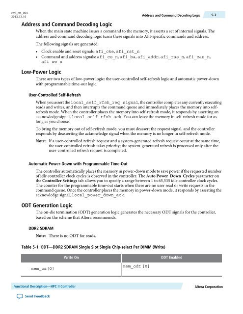
Table 5-1: ODT—DDR2 SDRAM Single Slot Single Chip-select Per DIMM (Write)<br />
Write On<br />
ODT Enabled<br />
mem_cs[0]<br />
mem_odt [0]<br />
<strong>Functional</strong> <strong>Description</strong>—<strong>HPC</strong> <strong>II</strong> <strong>Controller</strong><br />
<strong>Altera</strong> Corporation<br />
Send Feedback


