


Create successful ePaper yourself
Turn your PDF publications into a flip-book with our unique Google optimized e-Paper software.
<strong>Grundfos</strong> E-<strong>pumps</strong><br />
3<br />
External setpoint signal<br />
The setpoint can be remote-set by connecting an<br />
analog signal transmitter to the input for the setpoint<br />
signal (terminal 4).<br />
Setpoint<br />
External setpoint<br />
signal<br />
Fig. 41 Actual setpoint as a product (multiplied value) of<br />
setpoint and external setpoint signal<br />
Select the actual external signal, 0-10 V, 0-20 mA,<br />
4-20 mA, via the R100. See section External setpoint,<br />
page 32.<br />
In control mode "Controlled", the setpoint can be set<br />
externally within the range from sensor min to the<br />
setpoint set on the pump or via the R100.<br />
[m]<br />
Actual<br />
setpoint<br />
Actual setpoint<br />
Sensor max<br />
Actual setpoint<br />
Setpoint set via the control<br />
panel, R100 or PC Tool<br />
E-products<br />
Sensor min<br />
External setpoint signal<br />
0 10 V<br />
0 20 mA<br />
4 20 mA<br />
Fig. 42 Relation between the actual setpoint and the<br />
external setpoint signal in control mode<br />
"Controlled"<br />
Example: At a sensor min value of 0 psi, a setpoint set<br />
of 50 psi and an external setpoint of 80 % (an 8V<br />
analog signal to Terminal 4 if using an analog signal of<br />
0 - 10V), the actual setpoint will be as follows:<br />
Actual setpoint = (setpoint - sensor min) x % external setpoint +<br />
sensor min<br />
= (50 - 0) x 80 % + 0<br />
= 40 psi<br />
TM03 8601 2007<br />
TM02 8988 1304<br />
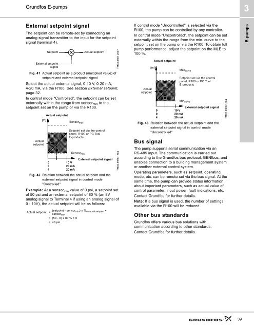
If control mode "Uncontrolled" is selected via the<br />
R100, the pump can be controlled by any controller.<br />
In control mode "Uncontrolled", the setpoint can be set<br />
externally within the range from the min. curve to the<br />
setpoint set on the pump or via the R100. To obtain full<br />
pump performance, adjust the setpoint on the MLE to<br />
100 %.<br />
[m]<br />
Actual<br />
setpoint<br />
External setpoint signal<br />
0 10 V<br />
0 20 mA<br />
4 20 mA<br />
Fig. 43 Relation between the actual setpoint and the<br />
external setpoint signal in control mode<br />
"Uncontrolled"<br />
Bus signal<br />
Actual setpoint<br />
Max curve<br />
The pump supports serial communication via an<br />
RS-485 input. The communication is carried out<br />
according to the <strong>Grundfos</strong> bus protocol, GENIbus, and<br />
enables connection to a building management system<br />
or another external control system.<br />
Operating parameters, such as setpoint, operating<br />
mode, etc. can be remote-set via the bus signal. At the<br />
same time, the pump can provide status information<br />
about important parameters, such as actual value of<br />
control parameter, input power, fault indications, etc.<br />
Contact <strong>Grundfos</strong> for further details.<br />
Note: If a bus signal is used, the number of settings<br />
available via the R100 will be reduced.<br />
Other bus standards<br />
Setpoint set via the control<br />
panel, R100 or PC Tool<br />
E-products<br />
Min curve<br />
<strong>Grundfos</strong> offers various bus solutions with<br />
communication according to other standards.<br />
Contact <strong>Grundfos</strong> for further details.<br />
TM02 8988 1304<br />
E-<strong>pumps</strong><br />
39


