


Create successful ePaper yourself
Turn your PDF publications into a flip-book with our unique Google optimized e-Paper software.
9<br />
<strong>Grundfos</strong> E-<strong>pumps</strong><br />
Frequency-controlled operation<br />
The same formula cannot be used for the calculation of<br />
the power input in connection with motors with<br />
variable frequency drives. In fact, in this case, there is<br />
no safe way of calculating the power input, based on<br />
simple current and voltage measurements, as these<br />
are not sinusoidal. Instead, the power must be<br />
calculated by means of instruments and on the basis of<br />
instantaneous measurements of current and voltage.<br />
If the power (P) is known as well as the RMS value of<br />
current and voltage, the so-called power factor (PF)<br />
can be calculated using this formula:<br />
Unlike what is the case when current and voltage are<br />
sinusoidal, the power factor has no direct connection<br />
with the way in which current and voltage are<br />
displaced in time.<br />
For MLE motors the following values are provided as a<br />
guideline to the power factor depending on motor size:<br />
Three-phase MLE motor<br />
3600 rpm<br />
[Hp]<br />
PF = ---------------------<br />
P<br />
3 UI<br />
Power factor<br />
(PF)<br />
1.0 0.73<br />
1.5 0.83<br />
2.0 0.87<br />
3.0 0.91<br />
5.0 0.92<br />
7.5 0.94<br />
10 0.93<br />
15 0.89<br />
20 0.89<br />
25 0.88<br />
30 0.88<br />
When measuring the input current in connection with<br />
installation and service of a system with a variable<br />
frequency drive, it is necessary to use an instrument<br />
that is capable of measuring "non-sinusoidal" currents.<br />
In general, current measuring instruments for variable<br />
frequency drives must be of a type measuring "True<br />
RMS".<br />
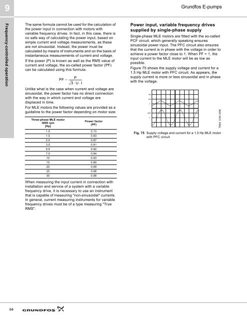
Power input, variable frequency drives<br />
supplied by single-phase supply<br />
Single-phase MLE motors are fitted with the so-called<br />
PCF circuit, which generally speaking ensures<br />
sinusoidal power input. The PFC circuit also ensures<br />
that the current is in phase with the voltage in order to<br />
achieve a power factor close to 1. When PF = 1, the<br />
input current to the MLE motor will be as low as<br />
possible.<br />
Figure 75 shows the supply voltage and current for a<br />
1.5 Hp MLE motor with PFC circuit. As appears, the<br />
supply current is more or less sinusoidal and in phase<br />
with the voltage.<br />
Fig. 75 Supply voltage and current for a 1.5 Hp MLE motor<br />
with PFC circuit<br />
TM02 1236 3396<br />
64


