


Create successful ePaper yourself
Turn your PDF publications into a flip-book with our unique Google optimized e-Paper software.
<strong>Grundfos</strong> E-<strong>pumps</strong><br />
5<br />
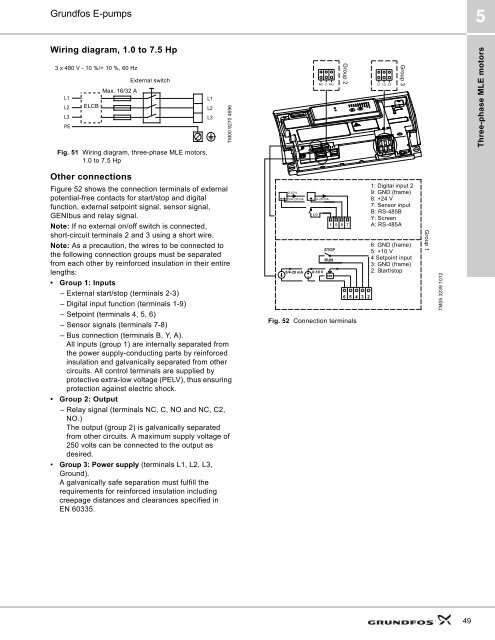
Wiring diagram, 1.0 to 7.5 Hp<br />
3 x 480 V - 10 %/+ 10 %, 60 Hz<br />
L1<br />
L2<br />
L3<br />
PE<br />
ELCB<br />
External switch<br />
Max. 16/32 A<br />
L1<br />
L2<br />
L3<br />
TM00 9270 4696<br />
Group 2<br />
Group 3<br />
Three-phase MLE motors<br />
Fig. 51 Wiring diagram, three-phase MLE motors,<br />
1.0 to 7.5 Hp<br />
Other connections<br />
Figure 52 shows the connection terminals of external<br />
potential-free contacts for start/stop and digital<br />
function, external setpoint signal, sensor signal,<br />
GENIbus and relay signal.<br />
Note: If no external on/off switch is connected,<br />
short-circuit terminals 2 and 3 using a short wire.<br />
Note: As a precaution, the wires to be connected to<br />
the following connection groups must be separated<br />
from each other by reinforced insulation in their entire<br />
lengths:<br />
• Group 1: Inputs<br />
– External start/stop (terminals 2-3)<br />
– Digital input function (terminals 1-9)<br />
– Setpoint (terminals 4, 5, 6)<br />
– Sensor signals (terminals 7-8)<br />
– Bus connection (terminals B, Y, A).<br />
All inputs (group 1) are internally separated from<br />
the power supply-conducting parts by reinforced<br />
insulation and galvanically separated from other<br />
circuits. All control terminals are supplied by<br />
protective extra-low voltage (PELV), thus ensuring<br />
protection against electric shock.<br />
• Group 2: Output<br />
– Relay signal (terminals NC, C, NO and NC, C2,<br />
NO.)<br />
The output (group 2) is galvanically separated<br />
from other circuits. A maximum supply voltage of<br />
250 volts can be connected to the output as<br />
desired.<br />
• Group 3: Power supply (terminals L1, L2, L3,<br />
Ground).<br />
A galvanically safe separation must fulfill the<br />
requirements for reinforced insulation including<br />
creepage distances and clearances specified in<br />
EN 60335.<br />
Fig. 52 Connection terminals<br />
1: Digital input 2<br />
9: GND (frame)<br />
8: +24 V<br />
7: Sensor input<br />
B: RS-485B<br />
Y: Screen<br />
A: RS-485A<br />
6: GND (frame)<br />
5: +10 V<br />
4 Setpoint input<br />
3: GND (frame)<br />
2: Start/stop<br />
Group 1<br />
TM05 3239 1012<br />
49


