


You also want an ePaper? Increase the reach of your titles
YUMPU automatically turns print PDFs into web optimized ePapers that Google loves.
<strong>Grundfos</strong> E-<strong>pumps</strong><br />
6<br />
Connecting sensor and equipment on<br />
other low-voltage inputs<br />
All connections to control inputs (terminals 1-9, 9-10,<br />
and 9-11) should be made with screened cables.<br />
To obtain an efficient EMC protection, the screen must<br />
be connected to ground/frame in both ends and be<br />
unbroken between the two connection points.<br />
It is important that the screen is connected to<br />
ground/frame as direct as possible, i.e. by means of a<br />
metal cable bracket to encircle the screen completely.<br />
See fig. 57.<br />
To ensure a good connection between the cable<br />
bracket and ground/frame, any painting and surface<br />
treatment on the metal surfaces must be removed.<br />
• If the E-pump is connected to an electronic unit,<br />
control panel, etc. with a cable clamp identical to the<br />
one on the E-pump, the screen must be connected<br />
to this cable clamp. See fig. 58.<br />
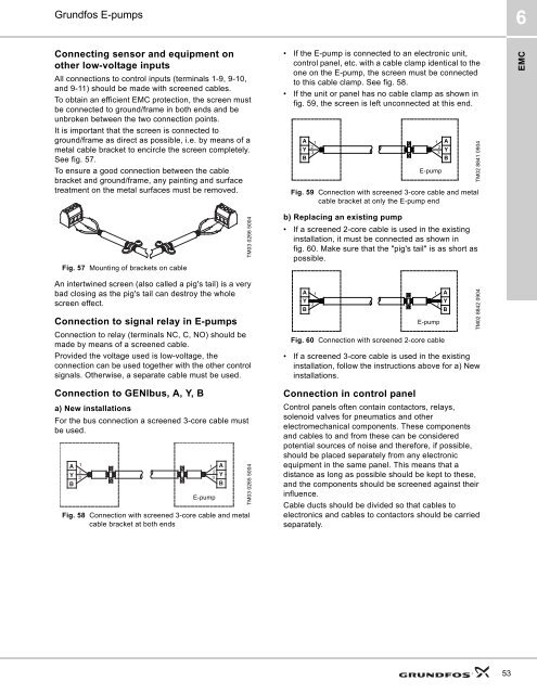
• If the unit or panel has no cable clamp as shown in<br />
fig. 59, the screen is left unconnected at this end.<br />
A<br />
Y<br />
B<br />
1<br />
2<br />
3<br />
E-pump<br />
1 A<br />
2<br />
Y<br />
3<br />
B<br />
Fig. 59 Connection with screened 3-core cable and metal<br />
cable bracket at only the E-pump end<br />
TM02 8841 0904<br />
EMC<br />
Fig. 57 Mounting of brackets on cable<br />
TM03 0266 5004<br />
b) Replacing an existing pump<br />
• If a screened 2-core cable is used in the existing<br />
installation, it must be connected as shown in<br />
fig. 60. Make sure that the "pig's tail" is as short as<br />
possible.<br />
An intertwined screen (also called a pig's tail) is a very<br />
bad closing as the pig's tail can destroy the whole<br />
screen effect.<br />
Connection to signal relay in E-<strong>pumps</strong><br />
Connection to relay (terminals NC, C, NO) should be<br />
made by means of a screened cable.<br />
Provided the voltage used is low-voltage, the<br />
connection can be used together with the other control<br />
signals. Otherwise, a separate cable must be used.<br />
Connection to GENIbus, A, Y, B<br />
a) New installations<br />
For the bus connection a screened 3-core cable must<br />
be used.<br />
A 1<br />
2<br />
Y 3<br />
B<br />
Fig. 58 Connection with screened 3-core cable and metal<br />
cable bracket at both ends<br />
1<br />
2<br />
3<br />
E-pump<br />
A<br />
Y<br />
B<br />
TM03 0265 5004<br />
A<br />
Y<br />
B<br />
1<br />
2<br />
E-pump<br />
1 A<br />
Y<br />
2<br />
B<br />
Fig. 60 Connection with screened 2-core cable<br />
• If a screened 3-core cable is used in the existing<br />
installation, follow the instructions above for a) New<br />
installations.<br />
Connection in control panel<br />
Control panels often contain contactors, relays,<br />
solenoid valves for pneumatics and other<br />
electromechanical components. These components<br />
and cables to and from these can be considered<br />
potential sources of noise and therefore, if possible,<br />
should be placed separately from any electronic<br />
equipment in the same panel. This means that a<br />
distance as long as possible should be kept to these,<br />
and the components should be screened against their<br />
influence.<br />
Cable ducts should be divided so that cables to<br />
electronics and cables to contactors should be carried<br />
separately.<br />
TM02 8842 0904<br />
53


