


You also want an ePaper? Increase the reach of your titles
YUMPU automatically turns print PDFs into web optimized ePapers that Google loves.
3<br />
<strong>Grundfos</strong> E-<strong>pumps</strong><br />
E-<strong>pumps</strong><br />
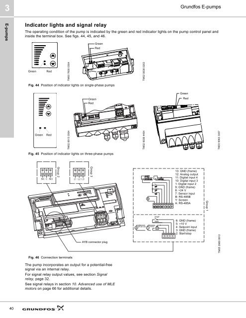
Indicator lights and signal relay<br />
The operating condition of the pump is indicated by the green and red indicator lights on the pump control panel and<br />
inside the terminal box. See figs. 44, 45, and 46.<br />
Green<br />
Red<br />
Green<br />
Red<br />
TM00 7600 0304<br />
TM02 0838 0203<br />
Fig. 44 Position of indicator lights on single-phase <strong>pumps</strong><br />
Green<br />
Red<br />
Green<br />
Red<br />
Green<br />
Red<br />
TM02 8513 0304<br />
TM02 9036 4404<br />
TM03 9063 3307<br />
Fig. 45 Position of indicator lights on three-phase <strong>pumps</strong><br />
NC C NO<br />
Group 2<br />
L1 L2 L3<br />
Group 3<br />
13: GND (frame)<br />
12: Analog output<br />
11: Digital input 4<br />
10: Digital input 3<br />
1: Digital input 2<br />
9: GND (frame)<br />
8: +24 V<br />
7: Sensor input<br />
B: RS-485B<br />
Y: Screen<br />
A: RS-485A<br />
Group 1<br />
AYB connector plug<br />
6: GND (frame)<br />
5: +10 V<br />
4: Setpoint input<br />
3: GND (frame)<br />
2: Start/stop<br />
TM05 2980 0812<br />
Fig. 46 Connection terminals<br />
The pump incorporates an output for a potential-free<br />
signal via an internal relay.<br />
For signal relay output values, see section Signal<br />
relay, page 32.<br />
See signal relays in section 10. Advanced use of MLE<br />
motors on page 66 for additional details.<br />
40


